QB Express
Issue #25 ~ October 31, 2007
"A magazine by the QB community, for the QB community!"
In This Issue
Editors
- Pete Berg
- Imortis Inglorian
- MystikShadows
Contributors
- Deleter
- redcrab
- Lachie Dazdarian
- notthecheatr
- Dean Menezes
- Codemss (RubyNL)
- Mentat
- Pritchard
- Michael D.
- sir_mud
- Regular Columns
- Articles & Editorials
- Tutorials
From The Editor's Desk
Written by Pete
HAPPY HALLOWEEN!
Welcome to a spook-tacular, spine-tingling Halloween issue of QB Express!
Okay, granted, the issue really has nothing to do with Halloween other than this opening letter and it's just a coincidence that this issue is coming out on October 31st (since I was too busy to release it earlier)...but HEY, why not celebrate if we have the chance?
In honor of this special day, I would like to bring your attention to one of the forgotten gems of the QBasic community, that 1994 horror adventure hit, Haunted Halloween by Jason Jackson.
It's an epic and scary adventure, all right. Here's the setup:
IT IS HALLOWEEN 1994, AND YOU AND A FRIEND HAVE BEEN INVITED TO A HALLOWEEN PARTY. WHILE DRIVING DOWN A ROAD AN ANIMAL JUMPS IN FRONT OF YOUR CAR. YOU SWIRVE TO AVOID HITTING IT. IN THE PROCESS YOU GET TWO FLAT TIRES. YOU LOOK IN YOUR TRUNK ONLY TO FIND ONE SPARE TIRE. YOU SEE A HOUSE IN THE DISTANCE, AND DECIDE TO GO GET HELP WHILE YOUR FRIEND STAYS IN THE CAR.
And what follows is, as you can tell by the screenshot below, probably the scariest adventure you will ever face in your life!

Download Haunted Halloween here: HH22.bas
On a side note, I believe I neglected to tell you the full title of this game: Haunted Halloween - How to Abuse the GOTO Statement. If you're looking for the perfect teaching primer on how to create spaghetti code, this would be it! Be sure to check it out, definitely worth a look.
Anyway, lots of good stuff this month...but you already knew that. Enjoy QB Express #25!
-Pete
A big thanks goes to Imortis Inglorian for doing just about everything this month except for write a few lame little bits like this one, heheh.
Submit To QB Express
You all know the drill. This magazine can't exist without people SUBMITTING articles, editorials, tutorials, reviews, news and feedback. This is not just a solo effort by me... it's a group effort by people throughout the QB community. If you have anything to submit, or have time to write something, DO IT!
If you want to write about something, but can't think of a topic, or need inspiration, check out the "Official QB Express Article Requests" thread! There have been quite a few articles requested -- and even if none of them strikes your fancy, we can help you come up with something that you would like to write about. If you're interested in getting your own monthly column or just want to write an article or two, by all means, do it! Anything that is submitted will be included!
I also want feedback and letters to the editor regarding this magazine. I want suggestions and critiques. What do you like? What don't you like? What could be done better? Let me know!
All submissions and feedback can be sent to qbexpress@gmail.com. You can also PM me on the Pete's QB Site or QBasic News message forums. If QB Express is going to continue to be so good, YOU need to contribute!
-Pete
Letters
Letter From Lachie Dazdarian
The usual congratulations on the last issue are in order. I
can't compliment you much on the News Briefs as I compiled a great
deal of it, so reading it wasn't interesting as usual. I was also
tad annoyed you missed to include my latest version of News Briefs
which included news on ciw1973's compo (really nicely compiled) and
dozen of nitpicks on other news. And they were sent few days before
you released issue #24. Oh, well.
Anyway, really nice content in the last issue.
Qlympics results were interesting to read. I was somewhat annoyed
with few winners, but that again is the result of few poor nomination
choices by my opinion. ZeroG is really far from the best action game
for that period of time. I mean, I can't even try to compare it with
TerraScape. But it seems a great deal of people simply WANTS to ignore
TerraScape for some reason. But if not TerraScape, Squealer TNT was a
much better choice too. Call me moaner, but I just don’t get this.
Also, I think most were too trigger-happy with Lynn's Legacy giving
it few undeserved awards. I'm mainly referring here to sound, where
The Quest For Opa Opa convincingly features the best work.
YAGL is another poor choice. A library that was soon abandoned after
first half-baked release, a library in which nobody coded anything notable
or complete, and a library that is basically a front-end for OpenGL.
Other choices are fine by me and I don't have anything to complain there. Yes.
Now I know I'm repeating myself, but this job should really be left to a panel of
judges who, if can't be objective, at least will play/test/read all the nominated
entries.
To continue.
It was really nice to see another game design related tutorial in the magazine.
Very nicely written article Joe King, and thank you for that.
RubyNL’s tutorials were a rather refreshing addition to the magazine, especially
in the style they were written. To bad they were for QB. :P
Also, interesting to see Pritchard’s articles in QBE, wouldn’t you say so?
I didn’t get FBHacker Series tutorial. It seems like a joke to me, but the author
appears to be more serious that he should. It’s just that sort of content I wish
people would think twice before submitting.
Anyway, good luck with this and next issues.
See you around.
Lachie Dazdarian - The Maker Of Stuff
Thanks for the feedback, Lachie! As for your assessment of the Qlympics results, I agree with you on many points. The best nominee (in my opinion) didn't always win, and Lynn's Legacy probably got a few too many awards. But then again, we awarded everything democratically, by a popular vote, and so the results showed us how the community as a whole feels - not just a few "elite" judges.
There's certainly a lot of value to a popular, democratic process. Then again, I personally prefer having a panel of considerate judges, because it usually results in every nominee getting a fair shake, and the best of the best, even if it's less popular, getting recognized. I bet most of the voters hadn't played even half of the games on the ballot, and thus voted for the ones they knew, based on name alone (Lynn's Legacy, The Griffon Legend), and some really quality titles missed out as a result.
In film, it's the difference between the People's Choice Awards and the Oscars. Which do we take more seriously as a culture? The democratically-awarded trophies that go to whichever movie had the best marketing campaign, or the awards carefully considered by a panel of industry experts? The people don't always make the best choice.
-Pete
Letter from MystikShadows
What a read this one was. It always amazes me to see just
how much creative power there is in all that contribute. Just
look at all the stuff there was for us to read this issue? I
mean wow. Two thumbs up to everyone involved. 24 issues now,
and a 25 that pomises to be yet another classic. QB Express is
breaking alot of records and getting the expectations of it's
users to a higher level with all the great contents. I think
the contributors are definitaly attempting to respond to that
higher expectation in a great way. As I said before, we're all
growing, we're all doing different thinng (me taking on a game
project like Color Triple Yahtzee! is a good example of that
hehe). with these new directions comes new needs, new research,
new subject that need to be talked about, discussed, taught
(in he form of new tutorials) in subjects that just weren't
talked about before. As we can all see here, this is being
covered bery nicely by the contributors, all of them.
First, the QLympics, You know, it seems alot happened since the
start of this great idea. including the one year hiatus of QB Express.
To me, I think thtat was the part of the problem. Alot happens in a
years, and the suggestions and submissions are probably what left
QLympics fans on the drop some. Next time this event happens I think
there will be alot of new things there that weren't even considerd
before. I'm glad I got the runner up I I wonder how that's gonna
fit next year :-). But I should have more stuff in my arsenal by
then hehe. I think though that there's alot of lessons that got
learn during this current QLympics that will just make next year's
event much better than this year. In the submissions that were
made and voted for however, I think all the top winners and runner
ups (including me hehe) got their well deserved recognition. I think
it ended up beign a pretty good event even if certain things weren't
there. :-).
How about that news section? I like to think I cover the grounds
pretty good as far as keeping myself up to date on what's going on but
there's alot of thinsg I didn't know about in that news section. Alot
of great stuff, great projects, I think i'll need to work harder to
"really" keep myself up to date, or just wait for the next issue since
it's all being covered so nicely. The cartoons are great once again.
I still get a smirk from looking at diffeecult's high level programming
cartoon, I really like his humor hehe. The other cartoons were as expected,
as funny as they can, great originality, awesome stuff. And you know, when
you think about it, none of this is really surprising to see considering
where we all stand today.
One of the project news that caught my eyes is definitaly VISG GUI builder
mrhx definitaly seems to be on the right track for this. I think it's
really gonna help FB make it's mark as a true windows languages when tools
like this take alot out of Windows API coding just to get an application
off the ground. I hope this one is pushed far, it's a great idea, much
needed. Though maybe it's windows only, atleast, using the API like that,
it will make very streamlined windows applications compared to using things
likes wxWidgets on windows. So I think it's a great concept that should be
taken as far as they can.
I gotta hand to lachie, it's no wonder he has the FB Game website and such,
it's amazing how much detail he puts into all his reviews and the review on
lodestar was no exception. He has a knack for taking the good and useful
information about a game to create his review from and really knows how to
present this information to the readers. I've seen other good ones, but
Lachie really takes it home. Two thumbs up for his work. I know I appreciate
it, and I'm sure i'm not the only one. Looking forward to reading more of his
reviews. And while I'm on the lachie subject, I really liked his highscore
tutorial. I think there hsould be more tutorials that talk about these side
features that help make a game more complete, things like that highscore
feature, maybe tips and tricks or simple reviews of what people like to see
in a game. How important is the ending for example, when you loose and when
you win. How to score during the game play, who bonuses are so motivating
to try to get, and a whole bunch of other side subjects like that I think
can be quite a successful set of articles especially for newcomers to the
game development scene (like me lol).
RubyNL, I have to say it's a rather new name for me, atleast I never noticed
it too much before. But I think the time based motion & collision detection
tutorial is gonna help me, and many others remember the name well. what a
great tutorial. Great way to explain everything covered in the totorial,
not affraid to use graphics and images to make the points being covered. I
think RubyNL is gonna become quite the name if tutorials like that are
being submitted continuously. I enjoyed it from start to finish. Very well
done. Of course, the swirl effect tutorial was an interesting read too.
Yes, I wan to read more from RubyNL.
Mentat's Wireframe, I can't finish this letter before talking about that.
I was first introduced to wireframe graphics back in the late 70s with a
language called MIRA. Back then, MIRA was THE language for 3D Graphics, in
fact it was the only language for 3D graphics aside using assembler and C.
Anyway, Since then, I've read more than one book / aritcle on wireframe
graphics, and I think I can say that mentat's way of explaining it finally
kicked in for me. I learned alot from relsoft's series of course, but
there's something about mentat's way of putting it so to speak that just
made sense to the way I read I guess. :-). Great work there too.
Dean Menezes' Searching Algorithm binary tree was one of the more informative
tutorials I've read. Another fella that seems to have the knack for presenting
the theory in such a way that it becomes a natural process to absorb the knowledge
he has to sure. Systematic, from start to finish, each item either describing or
announcing what's up ahead, seems like just a great wayt o go about teaching a subject,
any subject. I definitaly want to read more from Dean, so crack your fingers and get
writing Dean ;-).
FBHacker Series: I think has got to be the most original means of teaching
programming I've ever seen. You basically learn as you play the role of a
hacker. I've been there when this idea saw birth back then. And still today,
I can't think of a more original and enticing way to learn programming. When
done, I don't have a single doubt that FB Hacker is gonna be one for the books.
It's a great concept that has all the look, feel and potential to be a real
breakthrough way to teach the subject at hand. Awesome work so far and well,
can't wait to see where it will all go.
The FBGfx buffer tutorial by Pritchard was pretty good. For one thing, the
Image datatype is a new thing to me, I didn't know about it till I read his
tutorial. I think this is a great way to allow to use and manipulate imnages.
So not only did I learn something new about FB, but I think Pritchard's described
how to use it pretty well. As the whole world knows I'm not much into graphics
(atleast not yet, lol). But yeah, tutorials like this one is what's getting me
more into the subject. So it was an interesting read for me.
Finally Stylin's XCP series is very interesting. I like where the idea came from
and so far, I really like what he is including in the series so far. It will be a great
source of information for anyone (newcomer or not) I think everyone will have something
to learn about from this series. I'm not sure what's up a head, what he wants to talk
about next, but I for one can't wait to read about it. Great idea and great work so far.
In a general way, all I can say is that it's really great seing how every article that
make up each issue is so varied but useful to all of us I think. It just goes with the way
we're all learning and where we're going with this knowledge. I can't wait to see what
the line up is gonna be in the next issue but I bet it's gonna be a perfect reflexion of
where things are abnd where we're ALL going, as it uisually been, in every issue, so far.
Great work to all and I talk to you all next month.
MystikShadows
Stephane Richard
Thanks for all the praise of last months issue. I was rather happy with it myself.
One note about FBHacker though, and this addresses Lachie's letter as well.
The originator of FBHacker, Shawn Hartnell, had not meant for all of them to be
published all at once. Just a case of me an Pete having a lack of communication.
The Original Idea was to post one at a time, and then in the next issue, post a
short tutorial like solution to the last one, plus a new one. Sort of like
a crossword puzzle.
I am truely sorry to Shawn Hartnell for my slip up on this one, and I am also
sorry to readers who may have totaly missed the point of FBHacker as a result.
Oh well. There is always the future, right?
-Imortis Inglorian (Luther Ramsey)
Letter from notthecheatr
Hey Pete, notthecheatr writing this since you said you hadn't
gotten any letters yet. Glad that another issue of QB Express is hitting the
net, though it's a shame people haven't been submitting as much yet. I hope QBE
continues to thrive, as it is (at least for me) one major benefit of the community - I've
never seen any net magazine which I enjoyed as thoroughly as this one.
I'm not sure what all is going into this issue, but I'll just talk about some
of the interesting things I've seen on the forum lately that may or may
not go into this issue. If I start to ramble, just press page down a few
times and I'll return to reality ;-)
One of my favourite things this month was all the graphics demos and
things by KristopherWindsor. He posted a bunch of them in a single thread,
some simple but some plenty interesting, then posted a really great
tutorial about how one of them works- I hope that tutorial makes it into
the magazine.
There is of course my tutorial, written for fun because I've been playing around
with particles all week and I figured if I'm going to write a particle engine, I might
as well write some tutorials alongside it so everyone can see how it's done... or how
NOT to do it, anyways :P
freeLOLcode by sir_mud has easily PWNed everyone with it's greatness, and I
suspect FreeBasic will be entirely replaced by LOLcode in the future... well maybe
not, heh.
Best of all has got to be the products of various people answering to the pointless
challenges of a certain QBasic fanatic whose purpose in life is apparently to ridicule
FreeBasic (and most of what he types is fud anyways, to quote v1ctor). As a result
of his charges, PCopy has now been implemented in FreeBasic, and much more
compatible to QBasic and useful than any other Basic language, and a
printing library has been written to make printing in Windows easier. Once again
FreeBasic stands up to the charges and more!
And of course we're starting to see playable demos for a number of games
(Pacenstein, a couple of RTS's, a space shooter) which indicates that we're going to
have some finished games coming up pretty soon... so I'd say the FB community is
alive and well, in spite of any failure on the part of people to submit to this months
QBE ;-) Don't worry, next month will probably be bigger, badder, and better than
usual, to make up for all this.
So anyways, I guess I'll finish my half-crazed ramblings... have a good month! I
await QBE 25 with bated breath! (I dunno, it's a literary cliche... I read a lot, yes
I know I'm a geek.)
I find it very cool that most of the people that read QB Express consider it one of their favorite magazines. Sure, we have pretty low readership in the grand scheme of things, but one of the most active reader bases anywhere. Here, the readers *are* the writers, and I'd say the majority of people who read QB Express every month and wait for it with "bated breath" have also contributed to the magazine.
Thanks to the Internet, we've really been able to innovate how media is produced, consumed and viewed -- and I think that's a very cool thing. Now, every month, rather than spending a half hour or an hour reading a magazine produced by a professional editorial staff that's well disconnected from the readers, we spend that time reading QB Express -- which might be a little rough around the edges and is certainly not professional by any means -- but it feels so much more direct and personal. This is "our" magazine, whereas I consider magazines created in the traditional way to be "theirs." And it's happening in all forms of media. How many of you spend more time watching YouTube videos than network television or big blockbuster movies? Sure, these viral videos are of shoddy quality, have blatantly low production values, and lack polish -- but they belong to us, the people. And it's something big companies will never quite understand.
-Pete
Have a letter for the editor? Send all your rants, raves, ideas, comments and questions to qbexpress@gmail.com.
News Briefs
Site News
- Imortis opened his personal webpage
-
Imortis, a community regular and QB Express co-editor, opened his personal website.
The site is planned to feature his tutorials, articles and programs, and he already
made a first update.
Visit the website on this link: http://www.zendurl.com/imortis/
News Brief by Lachie
Dazdarian
Project News
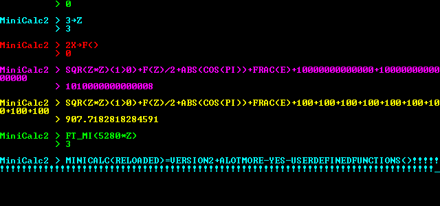
- MiniCalc FreeBASIC
-
Kristopher Windsor released a FreeBASIC version of his old MiniCalc program
(including many upgrades). MiniCalc is a console mode, command line based
calculator.
For a download visit this forum post.
News Brief by Lachie
Dazdarian
- FBWinPrint - A FreeBASIC Windows Printing Library
-
vdecampo released a FreeBASIC printing library. According to his words, it allows
the creation of a PrinterObject which helps in dealing with printing to the printer.
It also has some ancillary features like quick access to common dialogs like
open/save/printer/pagesetup/fonts/colors.
The current version is 0.12. For more information visit
this forum thread.
News Brief by Lachie
Dazdarian
- TOAOGS - Generic Game Server written in and for FreeBASIC
-
sir_mud released a generic game server in FB with a goal to greatly simplify
the process of making online/local network multiplayer games. The project is
currently in development, but there is a stable version available.
Visit the official project page for more information:
http://hmcsoft.org/p/toaogs.php
News Brief by Lachie
Dazdarian
- MP3 ReNamer by Rattrapmax6
-
Rattrapmax6 posted an MP3 batch renamer September 5th; it iterates
through all the MP3s in a directory and renames them to match their internal information tags. Though there are other programs that do this in Windows,
it was written specifically to provide that functionality for linux. His project
thread is here,
and the program was first uploaded to file-pasta (link may be broken).
News Brief by notthecheatr
- Prichard's FreeBASIC Torrents project
-
A know community member Pritchard started an interesting project whose goal
is for the community to share FB packages via batch torrents. The packages
are planned to contain FreeBASIC itself and FreeBASIC programs (utilities and
games), tutorials, code snippets and similar.
So far he released his first FB torrent entitled FBPackage Issue #1,
divided in several separate sections to download.
The project is still changing and developing, so visit
this forum
topic and support the project by seeding this package and posting suggestions.
News Brief by Lachie
Dazdarian
- PNGcustomfont ver.1.1
-
notthecheatr released another FreeBASIC font library, but this one is
the most complete one in FreeBASIC yet, featuring many fonts packed for
the library, plenty of examples, and a huge manual and a tutorial.
Library features, listed by notthecheatr:
- Support for 8-bit or 32-bit mode
- Loading of BMP or PNG fonts with many options
- Drawing with alpha channel or trans
- A QB-like cursor system with plenty of bells and whistles
- Clipping
- Buffered drawing
- Efficient memory usage
- Variable-width characters
- Font information is stored in an external file, not within the
image as in Draw String.
For more information look at his forum post, or
download the library here.
News Brief by Lachie
Dazdarian
- FreeLOLCode
-
sir_mud has released a library that allows FreeBasic to compile LOLcode.
LOLcode is something of a joke language, but it's powerful and fun. The forum post is here.
- CSGP : Cute Short Game Project : Announce of version 2.0
-
Yes after Over 18 months of existance... it's time for CSGP to grow
up!
Firstly by its new look , check it at http://csgp.suret.net
you can compare (for fun) with the old look ;P at
http://csgp.suret.net/indexv1.html
Secondly by its rules ... You know these strange utopic rules.
They still there but, with small changes
- Accept OpenGL as a natural FB gfx lib. (no CSGP title yet, but
...)
- Accept any FB compatible Sound Library
- Still refuse any resource files (bitmap or sound or others)
except if the program itself generate the files (ex : the embeded
level editor of CSGP Lander)
- Any GFX resolution... prefer low res, but since lander (vectorial
gfx
game) high res is better.
so to resume the new rule set version is:
- All; in 1 freeBASIC source file : one .BAS file that contains code
+
resource
- No extra library dependency : Only native FB libs except for sound
library
- Linux, Windows and as much as DOS compatible: no OS specific
API.
- no ASM / INP /OUT platform specific usage: no low level access
- .BAS file as short as possible: Comments are not counted ;) but the
idea is to have small executable
- As small s possible footprint memory usage : never waste
memory
- and of course have fun with it !
So now start a second step in the CSGP life
Enjoy and have fun !
News Brief by redcrab
Competition News
- ciw1973's competition results
-
On August 25th ciw1973 posted results on his more that succesfull
FreeBASIC game competition. The most noted competition rule was that
"pre-drawn graphics" were not allowed.
There were totally 8 entries, out of which 5 can be rendered as
complete.
ciw1973 was kind enough to award the two runners up (Mighy Line and
Zonaxtic!) with $50, together with $200 for the winner
(Catloaf 2600) as announced earlier.
The competition results, listed by final scores:
Congratulations go to Joe King for winning in a surprisingly tough
competition, and to ciw1973 for making the entire event such a success.
Check the competitions results thread here.
I think I can speak for most and say that we are impatiently waiting
for the next compo by ciw1973.
News Brief by Lachie
Dazdarian
If you have news to report, email it to us at QBExpress@gmail.com!
Gallery
Written by Imortis Inglorian
Every issue QB Express features a preview and exciting new screenshots from an upcoming QB/FB game. If you would like your game featured, send in some screenshots!
Asteroids Inspired Game
download link: Here
Notes from the author, speedlemon:
I'd like to mention that I tested it on 3 computers, and there
was a noticeable difference in the rate at which the enemies grew. In the
worst case, the game is unbeatable (still playable). Keep this in mind while
playing. However, the game, when played correctly, usually took me around
900 kills before I was able to all. In other words, you might think that
it is unbeatable, but the times that I beat it, it took me a good 5 minutes
or so (and the 5 minutes will be boring....) on design:
well, on this game, there wasn't one. I just started making it. That will explain the poor gameplay, etc.
I didn't make the graphics for this game-- You may or may not recognize them from Angband.
I took the time to play this little gem, and I must say that it's really
quite fun for it's simplicity. Aside from a few speed tweaks that need to be done and
some custom graphics, I'd say it's worthy of a play. If nothing else it will show you what
allegro can do.
More information can be found here.
The multi-faceted nature of games: the Dream, the Design, and the Reality:
Or how to stop hating your game and give it the attention it deserves
By Deleter
Now, I’m probably not the best person to be writing this article, as I
haven’t finished much of anything. On top of that I am planning to draw
analogies to real life things that I don’t any experience with, but to
present them as if I knew what I was talking about. If you are still here
then good, you’ve probably read my other stuff and are already used to the
fact that this is always true whether or not I say it. So onto the actual
article…
…So now, what is this three part description of a game, and why do you care?
Well the first part is obvious: The Dream. Everyone has them, many of them, in
fact sometimes it feels like there are too many of them, as everyone and his
nine-fingered sister has their own set of ideas for games. Dreams are the things
that make you go through the grueling process of coding and debugging. Dreams are
in short your games soul. They are the thing that all games start out as. And as
they are the most numerous, they are also the most fragile. Countless game ideas,
great ones included have been discarded on the side of the road, left to die.
Of course, some might view this as mercy compared to the necessary process of the
next step. It can be such a rigorous process, that some dreams are viciously ripped
apart by it and their creators are mentally scarred for life. This is the creation
of the Design. See, in their natural state dreams are like the random scraps that
hotdogs are made out of, though a lot more desirable. In fact that’s a horrible
analogy, but in any case the point is, dreams are not fit for consumption. They
need to be translated from the dream world to our world. This is the process of
designing. The important thing to consider is how you do it. Just plopping down
your dream into text will bring it somewhat into reality, but often this is a bad
way of doing it and leads to problems down the road. Now that’s not to say you
shouldn’t write down your ideas, it’s a good idea to start by doing that. But if
you really want to do it justice, you should do a lot more.
First of all, what is even more important than the idea is the idea of the idea,
your dream’s soul that is. What the heck do I mean? Well basically, if your dream
was murdered, what part of it would you remember? What is its essence? What is the
central part that all other parts of it point to? If you sat down in an interrogation
room with your dream and asked it who it really was, what would it tell you? If you
can answer any of these questions, the answer is your games soul. Finding it can really
be a pain, and sometimes your dream won’t make it out of that interrogation room. But
if the two of you come out alive, you are on your way to making something great.
So now that you have your game’s soul firmly in your grip, what now? Now you brainstorm,
find every possible element and part of your dream that complements its soul, and refine
the elements you had already thought of. Basically, build up your game idea, refine
your game idea, make your game’s soul shine. Now this process never ends throughout
your game’s life cycle, but the more you do in the beginning, the less refactoring
and reprogramming you are going to have to do, which is a plus. Once you are fairly
confident in what you have, make your design document. This is taking your concepts
and ideas, and bringing them into code/modeling/hard-core designing world. Write
some specifications for things, some implementation ideas, etc. There are much better
and more detailed guides for this process elsewhere so I won’t bog you down with a
mediocre one.
So now comes the real work. Yeah, you thought everything up to this point was hard?
Well give up now if you aren’t ready for a hundred-fold of everything you’ve done up
to this point. Still here? Good, games need dedication and perhaps a bit of
foolhardiness. If you are reading this you probably have some of the latter at least,
since you saw my name and still kept going. Now this isn’t a technical article, again
there are plenty of those, and even if they all suck that’s not what this is and if
that’s what you want then annoy me enough and I might consider writing something in
that vein, well that or adding you to my spam filter list. Instead I am going to try
and discourage you from writing your game. Not intentionally mind you, there are far
too few indie games as it is, but simply as a side effect of giving it straight as
it is.
Basically, making games is like having children. If you can’t help but love it, while
at the same time knowing every one of its flaws, while having it treat you like shit,
and still give it your all and more, then your game stands a chance. You may think
that sounds stupid or is wrong, or that I have no clue what I am talking about as I
have never had any children, and while that second point may be true, the first one
is not. You have to love your game and be dedicated to it if it’s going to make it to
completion. Laugh if you want, but I will only laugh back when your game becomes
nothing but lost bits after you erase it on your hard drive.
So again you are forced to do what you really don’t want to. You must know your game
in and out. Don’t lie to yourself about what sucks, know it. If you can, make it
better, but first thing always know everything about your game. No one should be able
to point out a flaw that you aren’t already aware of. Now I’m not talking about
programming bugs. I’m talking about design and implementation issues. The loading screen
is annoying, the so and so sound pisses people off, the reload counter is too long for
this, but can’t be any shorter because of this. This feature has been done better
already in other games, etc. The tricky part is admitting all these faults to yourself,
and still loving what you have. Know the good parts as well. Know how innovative your
control system is, know how good the explosions reward the player, know how well your
enemy designs stick in your player’s mind. Every change you make know what it makes
and what it breaks.
Now that you have it, use this knowledge to the best of your abilities. Balance elements
against each other until your game is as optimized as possible. Sometimes you will realize
that a certain feature has to be cut, or another one added for the good of several others.
It’s ok to do this now, though the sooner the better as it will mean less re-doing of stuff.
If you don’t like your game, know what you don’t like and make it better. And get outside
opinions, always get outside opinions. I have always found in the act of creation that my
own idea of my works is often skewed. I’ve liked what others haven’t, and found that things
I didn’t care for as much were generally enjoyed. As far as releasing is concerned what can
I say. You will never feel like your game is really ready, but at some point you just have
to come to terms with reality and release it. Fix up the bugs later if needed, make tweaks
whatever. But get it out there. Near the end of a project sometimes things get slow and this
can really invigorate you. I’m not saying to release an unready source, but talk with people
who have helped you and see what they think.
And with that I will leave you. I’ve already said more than I should and more than you care
to read I’m sure. Thanks if you’ve made it this far, you’ve been a great audience. Shoot any
comments to deleter8_at_gmail.com. Just don’t forget to love your game despite its flaws, if
you can do this and keep going, the world will thank you for the product you release. Good
luck and happy dreaming, designing, and realizing.
Accessibility and File Names
By notthecheatr
So you've written your first really cool program - or your
first tutorial - or your first web page. Got all those images
linked in, or perhaps you have some external .BI files included
in your program - you're going to release it on the web for all
to see. Generally you'd put these things into a ZIP, RAR, or 7z
archive (or tar.gz, or just tar, or even bz2... the list is
endless). Now presumably you want to include everyone - not
just people who use Windows. But there's a little secret most
Windows users don't know about Linux, and that is that filenames
in Linux are case-sensitive. What does that mean? That means that
"ABC", "abc", and "aBc" are ALL DIFFERENT. In Windows, this is no
problem. In DOS, no problem. In Linux, BIG problem - for when the
archive is extracted, the contents will make no sense, whether as
HTML with images or a program with external files.
Why do I bring it up? Lately there have been complaints that people
will use the wrong case. The file will be named "example.png" but in
the HTML or BAS file it's referenced as "Example.PNG" - or something
similar. Once again, this works just fine in Windows. It does NOT work in
Linux. For this reason, I stress the importance of using consistent case
throughout any project you use. In fact, unless capitalizing some letter in
the filename adds any extra meaning (usually it doesn't), I recommend you
don't use capital letters at all. In DOS, capital letters were pretty much
standard - probably to make case-insensitivity easier - but in linux, you can
have any case - but then you are case-sensitive, and you need to make sure you
get the right case. If you want to maintain DOS-similarity, you'll probably
have all letters capital and no letters lower-case. The important thing is
consistency, it really doesn't matter how you do it just so long as you do
it the same everywhere.
Of course, there is something a Linux user might be tempted to do that
wouldn't go over well in Windows - the Linux user might put several
different files with the same name but in different case in the same directory.
I can't imagine WHY anyone would do this, and I have never SEEN anyone do it, but
it is after all a possibility, and obviously this would cause major problems to
the innocent Windows user who attempts to extract the contents of that archive.
In summary: Name all files in a directory uniquely, and keep the case
consistent. This way your program, article, or web page will be accessible
to users on all platforms. Are we all agreed? Good.
User Oriented Programming
Written by Stéphane Richard (MystikShadows)
INTRODUCTION:
When you are cerating your applications or games it's very easy to drift off from the one important fact you should
never drift away from. Let's rule out your own personal projects that you make for yourself and yourself only. What's left? The projects (applications, tools, utilities or games) that
you make for other people to use or play with. Believe it or not, this can make the impact of your program that much different to the users
of it's users. User considerations thorughout your program is a way of showing that you put the extra effort in your
program to make it as easy to use or play for the user as possible.
This will be the main focus of this article. User Oriented Programming essentially means that whatever part of the program that needs something from the user needs to consider certain things. This can depend on more than one thing. But in general there's always a way to improve how your programs interact with the user.
We'll look at what can need user interaction, what's good to give back to the user, what's overkill and such things so that when you make your programs you can make sure to consider what you need to make using your program as pleasant as possible to the user. So let's get right to it.
USER PRESENTATION:
This is usually the first view that users get of your program. Attention to detail from the very start can make or break the success of your programs. This is regardless of it's it's a GUI application or a Text based application you still need to take care to present your application the right way to the user.
How can you tell how things should be presented? There's moer than one criteria to help you determine this. Let's take a look at them.
- What Type Of Program Is Being Presented:
If you're program is a game, it's important to give the user the impression that it's a game as soon as possible. A user shouldn't start your program and get the wrong impression from it. Same thing goes for business applications as well. If you are creating a spreadsheet application, it's good that the user sees that it's a spreadsheet application from the very first screen he'll see appear. The best way to get an
idea of how to present your program is to take a look at how other programs (much like yours) are presented. For example, if You open Microsoft Excel, when the program appears, you're in an empty spreadsheet document, you can see what you can do next pretty much fromt he very start. Same thing for Microsoft Word. Basically, you need to take the main function of your program as the guideline to what the user is going
to be seeing and allowed to do (more on this later).
- What Part Of The Program Is Being Presented:
This is where you decide what happens first and what happens next. Typically, in a game, you'd present the main gaming menu (maybe after a title page) from where the player can create his profile, start a game, view the highscores, etc. In a business application there's a couple more things to consider. When you start any Microsoft Office application, you are essentially taken to a new empty document/database/spreadsheet/presentation. This makes sense because each of these
applications deal with one thing only. In Excel, you'll be doing spreadsheets, that's all. On the other hand, if you take an accounting or business management package and start that, you'll typically be taken into somekind of menu because you'll usually have more than possible thing that you can do. For example, create customers, create invoices, manage your inventory and the likes. So you need to consider what your program has to offer to it's user. Are you managing more than one independant item in your program? Questions like this one can really help
determine what the user sees first.
- What is Important To See First In That Part Of The Program:
Let's use a billing system to best illustrate this. There's more than one available and when you open those modules up, you can be taken to two possible things. The first is an empty invoice waiting to be filled. Or, you can be taken to a list of existing invoices. Both are good methods, some creators simply though thta creating an invoice as soon as possible was important while others believed that seeing your invoices (and searching for them) was more important. Is one better than the other? I think in this case both can be very userful to have. Eventually you just need to reach a decision and follow up on it.
Once you worked out these starting issues, it doesn't stop there. I guess you can say that user oriented programming is kinda like error management, it's a big job to integrate after your program is done so it's a good idea to start your programming project with these items in mind right from the start so that the work can be integrated into the regular programming tasks and hence not seem as big as it is. The general rule of thumb to remember for these projects is: "The easier you make it for the user, the harder you make it on you, the programmer.". Knowing this, since you already know you have big job ahead of you, you might
as well break it down into small manageable parts throughout the project rather than putting it all in at the end of the project. You'll thank yourself later. Now what are the next steps? The very next step is all about where thinsg should be and how the user can access the features of your program.
USER NAVIGATIONS:
Once the user starts your program, it's very important that he doesn't have to look too long to find out what he's supposed to
do. One of the key things to remember is that everything should be acessible while at the same time not being hidden within to many levels if menus or sequences of actions fromt he user.
The main reason for that is that not many users like to have to remember six sequences of keys before they can perform an action. Since this is an article
on user based programming we'll be putting the user first here. Hence, if you want to know what the user might want to do, where he might expect things to be and the likes, there's more than one tool
to get that information. Let's take a look at some of the more common ones.
- You Are Your First Source Of Information:
Yes, that's where it all starts. You're a user of some application or another. You have your own expectations and wants when you open an application or game.
Hence when you create a game or program that will be used by others you need to take the time to use it yourself. IF you find a certain feature is way to difficult to reach or has to many steps to it chances are your users
are going to think the same thing. If you don't have a feature and wish you did put it, again, other users are probably going to want that feature too. So what you want as a user is the first
step to making a programs other will want to use.
- Pools And Surveys:
Of course, no one expects you to know everything that everyone might possibly want in your program. IF you happen to have a website or have access to a website it might be a great idea to create a survey (or more than one) about your program.
Ask the questions that you have doubts about and always leave a space to let the ones filling in the survey tell you what they think of the feature and why it must/should be there. Hence alot of the questions you might ask that offer a set of choice
in them might benefit from having an "Other" selection with a text box to let the user enter what they mean by other. The idea of the surveys to get answers to your questions fromt he perspective of the potential users so what they want is important as
it will tell you if you're on the right track or not. This means that the earlier you know what the users think and want, the fater you can change your program to accomodate that.
You can go on rtelated forums and ask questions there too without creatign a survey per se as well. Just make sure the forum is relevant to your project somehow to get at least a minimum of interest on the part of the memebers.
- How Do The Other Programs Do It:
If you know of a program that does a similar feature (or atleast a program that is aimed at the same industry or tupe of user you are aiming for) if you cna see how they do it, it might e a first vital hint as to how you should present your own feature.
IT gives you an idea of how high up in the priority list the feature is considered for one thing. There's a common accepted standard that says the easier it is ti reach a feature the more important it must be. Sure it depends ont he program you're looking at but all in all
you can learn alot from another program. Including if a feature should be there or not. If you don't see a feature in a similar program, maybe they have a good reason not to have it there. This can play both ways, maybe they didn't think of that feature at all which ends
up giving your project an edge if the feature is that important. So taking the time to look at other proejcts might prove more beneficial than you might think.
Of course, you can also ask friends, co workers, and other people live, in person or by telephone if you want. When it comes to gettign the answers you need for the success of your project I think there's no limit to what you can do without being considered a spammer. The earlier you can do this in your programming effort the less work it becomes to
take this new found knowledge and implement it in your own project. So then, assuming you did all this and you now have all the features you want to put in your program you need to define where they go and why. Here again you have more than one possible means of presenting the features. Let's take a look at the two most widespread ways of organizing an
application.
- The Method Based Approach:
This essential means that things are presented in the order they are to be executed. You have to create an invoice before you can print it, you might need to edit that invoice before printing it too which would give a
menu that has the New Invoice, Modify Invoice, Print Invoice in that order to mimic the way things need to execute themselves in. This is a typical scenario in alot of business applications. it's a logical way of presenting the features
that users of a specific domain are accustomed to since a lot (if not most) of the programs they user are based on this concept of sequence of steps. But oday, it is not the only way to go about things. Which brings the next item in this list.
- Using The Right Metaphore:
Yes, a metaphore, many programs can benefit form one of these. For example, Windows that most of your use to day is beilt around a metaphore. In the case of Windows it's a desktop metaphore. They try to mimic how you do things on the top of your desk. Today it's hard to imagine Windows working any other way. This concept of using a metaphore can be
one of the best things for your projects because it's becoming a growing want of the users. They don't want to use your program, they want to experience it so to speak. Taking the time to see if a metaphore can and should be used can prove one of the best
decisions you make for the success of your project.
So then, at this point you0 have your list of features, you hopefully made a choice as to which of the two methods above you will use for your project. All this should also give you a good base idea of the structure of your menus and overall user interface so far. Typically, everything that follows here is based on whether you used the Method Based Approach or the Metaphore Approach to your project. So what come snext
will be explained under both methods whenever it's necessary. The next step is to start implementing the features themselves, and yes, the method used will help define alot of what the data entry screens will look like and how they will behave, same thing for how reports will get generated (or how the sub sequent game screens would/should appear. What else is tehre to consider? Funny how I used consider here because
the next step is exactly that, User Considerations. But before we get into that let's take a little time to define what the users really are.
TYPES OF USERS:
Throughout your project development you need to remember that all in all, there are two distinct types of users you'll be coding your project for. In each of these groups there are sub groups that determine alot of things for you. But all in all everyone can be classified under the following two groups.
- The Mouse Users:
These are the people that don't believe a computer is complete without a pointing device. They are typically people that believe that
if you can't do it with the mouse, you can't do it at all. And yes, they exist out there. The main thing to consider for these users is to
make use of the mouse on atleast every important feature of your program while keeping things on par with the method used (method or metaphore) then
your mouse users can do what they need to and won't complain too much if a specific feature can't be done with the mouse (such as data entry screens but that too can be mouse oriented to a certain point.
- The Keyboard Users:
Of course these users don't care much for a mouse. Everything has to be done with keyboard and keyboard shortcuts. They love the function keys and well, every other key they see on a typical keyboard. They do not however like to relearn everything. So although the keyboard is
a must for all the features, it's important to keep things consisten trhoughout the project, as in, if one module uses F2 to open a file, any module in that program that need to open a file should also use F2. I believe that with just a bit of common sense you can create a very useable keyboard standard.
I may have exagerated my descriptions of these users, but the point of this article is to accomodate both extremes of the user base you might have to deal with. The bottom line, if your program works with the mouse or keyboard you can get that many more users just because of that one considerations. People like to work they way they work and
trying to impose a give way to them won't make them to fond of your prorgam. Is there certain projects or specific task that just acn'e be accomplished witht he keyboard or the mouse? Depending on the project I have to answer yes to that question. More often than none however you can and should accomodate for the keyboard and the mouse by default. And in the unlikely event that something needs to be done with only one of these input devices, state it clearly on the screen "this operation must be performed with the keyboard" so that the user doesn't need to try to do it with the mouse if he can't. (see the user feedback section below for more of these user feedback tricks.
And now let's take a look at what other considerations you can do for the users.
USER CONSIDERATIONS:
Are you thinking something like "Hey, did I do enough of that so far?" the answer is no. Let's not hide the facts, you're probably doing this project not just for others to use, you probably want to use it yourself too. Hence you might have your way of doing things and you'd like to see them in there right? At least some of them right? So where do you draw the line? The answer is you don't. But it doesn't mean you can't accomodate yourself
too in this. Back in your surveys, you could suggest your method of doing it, and seeing if people agree with them or not. Leave them as suggestions however, not as set in stone methods of operations. IF you like it that way, chances or so will others. Who knows, you might be lucky enough that the way you want everything to work is ok with your potential users so it's not a bad idea to suggest your ways as at least some of your potential users
might not have an idea of hwo to use the feature and might think your way seems logical and good.
I already mentioned some considerations throughout this article so far. Things like keeying the features as directly and quicly accessible as possible to minimize keyboard or mouse actions is one of them. Another one I mentioned is to keep things consistent (such as the F2 key always being used to open files and documents). These are very important things to consider. There is more hwoever. Let's take data entry into considerations. Data entry screens are of course the most user specific programs to write. Data Entry typically implies that something will get saved to somekind of file and hence the data provided by the user is very important. Users are human however, they do make mistakes
and as such there are more than one trick to help make lower (or sometimes even eliminate) human errors. They have a great deal to do with the controls you use on the forms in most cases. So let's see what role these controls play in the data entry process. This of course can be used in Text Based user itnerfaces and in Graphical user Interfaces alike.
- A Regular Text Box:
This is often used for to many purposes. There is no validation per se here. The user is allowed to enter pretty much whatever he wants into this type of coutrol. This could be used for fields suck as name, notes, and other information. For most other types of fields one of the following is probably a much more recommended way of entering values.
- Masked Text Box:
Even back in the days of DBase and Clipper (back in the 80s) this type of control has always been used to help minimize human error. Masked Input Boxes are created to allow only certain keys to be pressed and if there's a certain visual representation that need to be abided by, the Masked Text Box can be used fort that purposes too. Things like Zip Code, Postal Code (canadian zip codes), telephone numbers, Social Security numbers, credit card numbers and things like that can definitaly benifit from a Masked Text Box.
- Check Boxes and Radio Buttons:
These are controls that typically have 2 values, they are either selected or not, In the case of check boxes, each checkbox can be selected or not. Useful for quick options that can all be selected or not. Radio bottons are different from CheckBoxes because they only allow one of the list of radio buttons to be selected. If you have a list of fixed values from which only one can apply at one time, Radio Buttons are the type of control to use (provided not too many of them are needed.
- The Combo Box:
This is represented by a text box and a list of selectable items that can be brought down to allow to pick one of the available options. They can be play the role of Radio Buttons when you have a long list of possible options where only one needs to be selected.
- The Scroll Bar:
If you have a field that can only have a certain range of numerical values (for example a volume control for a MIDI player you are making) a scroll bar is a great visual way to allow the users to enter a value instead of keying it in directly.
There are more controls but typically the play the role of one of these. Things like Date Drop Down which are a Masked Text Box with a buttom on the right side to make a calendar appear to allow to select a date. And others. Basically, since these controls can be used it becomes impossible to enter a wrong value into the system thus eliminating human error (or at the very least keeping human error to a strict minimum. After that is in place, you can of course add data validation to the whole screen. For example, if certain fields must be entered (known as mandatory fields) you can do a check before exiting the form or saving the data to make sure that these fields really do have values in them and warn the user if they are missing. The combination of these two elements will make sure that what gets saved is valid.
And if there's valid data to begin with, chances are, valid data will come out of the system. So when data is a high priority element of your project, these techniques can really help you make sure that you get only good and valid data to begin with, to process, and most likely valid results from them (if you're making a report or something). There's one more form of user oriented programming I want to cover in this article and that is, of course, user feedback.
USER FEEDBACK:
Did you ever call the support department of a company, any company, got left there for a few minutes or a 1/2 hour without no one telling you what's going on? How does it feel? Did you know that your program, unless you make it do things otherwise, will treat your users exactly that way? In a sentence, this is what user feedback is all about, not leaving the user in the dark. Making sure he/she knows what's about to happen (especially of a complex process is about to occur). Letting them know how things are going, let them know if their choice was executed successfully or if a problem occured. user feedback has been implemented before, you can probably learn a whole lot about what type of feedback you need to include just by looking at other programs. User feedback is a very important aspect of any projects that will be used
by other users (this includes games and applications).
There are many things that can happen in a program. Some require more or less feedback to the user, This is were common sense and a bit of background knowledge is needed to determine where and when to give the user feedback. Here are some of the major situations where I believe user feedback becomes almost crucial.
- When Something Is About To Be Deleted Or Overwriten:
Whether it's a record in a database, a file or anything that already exists it's important to let the user know what he's about to do and give him a chance to cancel or confirm the operation. a message like "you're about to delete something" isn't good enough either, you need to give him more information like what exactly is about to be overwritten or deleted so that he/she is well informed to make his/her decision to overwrite or delete the item in question.
- When Something Is Going To Take Some Time:
Needles to say that if a process can take several minutes to complete it goes without saying that the user will want to know about it before the process occurs. In these cases I find it important to do the following. First, let the user confirm that he wishes to start the process. If he chooses to execute the process, given a progress of what's happening, a progress bar is a great way to do this so he can see quickly how much longer it's going to take. And a message at the stating that the
process finised successfully or what errors occured if any.
- When The User Is Expected To Do Something During A Process:
If the program needs the user to do something (enter values such as criteria for a search or a range of records to consider for a report, he should know so right away so he can provided the expected information and get the process started. like the above point a progress bar (if it's a lengthy process) and a message stating if things were successful or not and why come highly recommended. It's really all about making sure the user knows three things. 1. What's about to happen, 2. What is happening, 3. What happened. By folliwng these wherever an important thing is about to occur, it will help your program be that much more successful to the eyes of your user as they will not be left in the dark. Likewise, giving the right information will help them help you if they call you with one of these problems.
User feedback is a must, it's really the best thing to remember from this article. To determine what needs to be done where, put yourself in the shoes of your users. Try out everything before you publish your program. Once again, if there are places where you would have liked to know about something before executing a certain part of your project, chances are, yoru users will probably expect that too. So taking the time to see what's happening where and how important it is to you to know about them is a great first step to making sure user feedback is adequate throughout your project.
<.p>
Another important thing is that if one of the feedback means that the user can't perform his selected action to let him know, if at all possible, why he can't perform it. Maybe there's no paper int he printer, maybe the record he's working with is locked by some else in the syustem and he has to wait for that user to be done with that specific record, maybe the system resources are inssufficient for the needs of the application. No matter what the reason, lettign the user know will also help him make sure he can perform the action which is, let's face it, the main reason why he's using your application in the first place. So when you can know the reason why, don't be affraid to share it witht he user, he'll only appreciate your application more because of this little consideration.
AND IN CONCLUSION:
As you might have noticed, most of User Oriented Programming items I mentioned here involved more common sense than business knowledge per se. As a final note, I'd like to talk about business knowledge itself. In one speciial form. If your program is an accounting system, it's important that the terminology you use reflect the terminology used by your users (in this case, accountants). Just that fact, keeping the terminology domain specific like that, can often give the impact you need to make your program stand out from the rest as far as user consideration goes.
Hence you need to learn enough about the domain your project is created for in order to use the right terminology that your users, in that field, will expect to see. It's a small form of respect if you will, for the knowledge your users have and are accustomed to work with. It doesn't take that much time to learn the right terminology, and does make a big difference in the impact of your project. So it's a quick and valuable tool for your creations.
I could probably write a whole book on just this subject alone, there's so many considerations involved when creating an applciation for your users. I hope this article opened up your eyes and your mind for your future projects. However, it's very possible that I've left something out, or didn't detail a specific aspect enough. IF you want more details you can email me (email is below my signature below). And talk to me about it, if there's enough grey areas I will create a 2nd part to this article that will cover them. This subject is important in all your projects that you want others to use so let me know if there's somethign you'd want to know more about that has been mentioned here. Until next time, happy reading and coding.
MystikShadows
Stéphane Richard
mystikshadows@gmail.com
Fun with Recursion
Written by Dean Menezes
What is recursion? Well, according to Wolfram
Mathworld (http://mathworld.wolfram.com/), recursion
is
"A recursive process is one in which objects are
defined in terms of other objects of the same type.
..."
What does this mean?
Well, let's look at this recursive factorial function:
 FUNCTION Factorial (i)
   IF i=0 THEN
     Factorial=1
   ELSE
     Factorial=n*Factorial(n-1)
   END IF
 END FUNCTION
Basically, recursion is when a function or subroutine
calls itself. There is also mutual recursion:
FUNCTION ODD (X)
 IF X = 0 THEN ODD = 0 ELSE ODD = EVEN(X - 1)
END FUNCTION

FUNCTION EVEN (X)
  IF X = 0 THEN EVEN = -1 ELSE EVEN = ODD(X - 1)
END FUNCTION
Use of recursion in an algorithm has both advantages
and disadvantages. The main advantage is usually
simplicity. The main disadvantage is often that the
algorithm may require large amounts of memory if the
depth of the recursion is very large.
EXERCISES:
1. Write a subroutine using Recursion to print numbers
from n to 0.
Answer:
SUB NtoZero(n)
 PRINT n
 IF n>0 THEN CALL NtoZero(n-1)
END SUB
2. Write a sub using Recursion to print numbers from 0
to n.
Answer:
SUB ZeroToN(n)
 CALL XtoY(0, n)
END SUB

SUB XtoY (x, y)
 PRINT x
 IF x < y THEN CALL XtoY(x+1, y)
END SUB
3. Write a function using Recursion to reverse a
string.
Answer:
FUNCTION Reverse$(X$)
 IF x$="" THEN
   Reverse$=""
 ELSE
   Reverse$=LEFT$(X$, 1)+Reverse(RIGHT$(X$, LEN(X$)-1))
 END IF
END FUNCTION
RECURSION PART II
By Dean Menezes
In the previous section, I gave an introduction to
recursion and had you do some short exercises. In
this section, I will show some more applications of
recursion.
Euclid's algorithm is a recursive algorithm for
computing the GCF.
See if you can write a function that does this now.
OK, if you can't, that's fine. Now read this
description:
"Given two natural numbers a and b, not both equal to
zero: check if b is zero; if yes, a is the gcd. If
not, repeat the process using, respectively, b, and
the remainder after dividing a by b. The remainder
after dividing a by b is usually written as a mod b."
Now write the function based on the description.
Answer:
FUNCTION GCD(A, B)
 IF B=0 THEN EUCLID=A: EXIT FUNCTION
 EUCLID=GCD(B, A MOD B)
END FUNCTION
Tower of Hanoi:
The objective of the game is to move the entire stack
to another peg, obeying the following rules:
- Only one disk may be moved at a time.
- Each move consists of taking the upper disk from
one of the pegs and sliding it onto another peg,
on top of the other disks that may already be
present on that peg.
- No disk may be placed on top of a smaller disk.
Try to find out an algorithm for solving this tower on
your own.
Answer:
The algorithm for moving h disc from peg f to peg t,
with peg r being the remaining peg is:
- If h>1 then first use this procedure to move
the h-1 smaller disks from peg t to peg r.
- Now the largest disk, i.e. disk h-1 can be
moved from peg f to peg t.
- If h>1 then again use this procedure to move
the h-1 smaller disks from peg r to peg t.
Now, modify this existing code to put QBASIC code for
this algorithm into SUB MOVEPILE. MOVEDISC is a sub
to move a disc from peg START to peg FINISH.
DECLARE SUB INSTRUCT ()
DECLARE SUB AUTO ()
DECLARE SUB PLAYGAME ()
DECLARE SUB MOVEPILE (N%, START%, FINISH%)
DECLARE SUB MOVEDISC (START%, FINISH%)
DECLARE SUB SHOWDISCS ()
DEFINT A-Z
CONST NUMDISCS = 8
DIM SHARED TOWERS(0 TO 2, 1 TO NUMDISCS), TOP(0 TO 2), NUMMOVES AS LONG
CLS
TOP(0) = NUMDISCS: TOP(1) = 0: TOP(2) = 0
FOR I = 1 TO NUMDISCS
 TOWERS(0, I) = 9 - I
NEXT
LOCATE 1, 26
PRINT CHR$(218); STRING$(14, CHR$(196)); CHR$(191)
LOCATE 2, 26
PRINT CHR$(179); "TOWER OF HANOI"; CHR$(179)
LOCATE 3, 26
PRINT CHR$(192); STRING$(14, CHR$(196)); CHR$(217)
PRINT STRING$(80, CHR$(196))
PRINT
PRINT "1: AUTO"
PRINT "2: HUMAN"
PRINT STRING$(20, CHR$(196))
WHILE CHOICE$ <> "1" AND CHOICE$ <> "2"
 INPUT "CHOOSE ONE: ", CHOICE$
 CHOICE$ = LTRIM$(RTRIM$(CHOICE$))
WEND
IF CHOICE$ = "1" THEN CALL AUTO ELSE CALL PLAYGAME

SUB AUTO
 CALL SHOWDISCS
 CALL MOVEPILE(8, 0, 2)
END SUB

SUB INSTRUCT
 PRINT "The TOWER OF HANOI is a mathematical game or puzzle.  It consists"
 PRINT "of three pegs and a number of discs which can slide onto any peg."
 PRINT "The puzzle starts with the discs stacked in order of size on one peg."
 PRINT
 PRINT "The object of the game is to move the entire stack onto another peg,"
 PRINT "obeying the following rules:"
 PRINT TAB(2); CHR$(248); " Only one disc may be moved at a time."
 PRINT TAB(2); CHR$(248); " Each move consists of taking the upper disc from"
 PRINT TAB(4); "one peg and sliding it onto another peg, on top of any discs"
 PRINT TAB(4); "that may already be on that peg."
 PRINT TAB(2); CHR$(248); " No disc may be placed on top of another disc."
 PRINT "PRESS ANY KEY TO CONTINUE..."
 NULL$ = INPUT$(1)
END SUB

SUB MOVEDISC (START, FINISH)
 DIM T AS SINGLE
 TOWERS(FINISH, TOP(FINISH) + 1) = TOWERS(START, TOP(START))
 TOP(FINISH) = TOP(FINISH) + 1
 TOWERS(START, TOP(START)) = 0
 TOP(START) = TOP(START) - 1
 NUMMOVES = NUMMOVES + 1
 CALL SHOWDISCS
 T = TIMER
 WHILE TIMER - T < .2:
   IF INKEY$ = CHR$(27) THEN END
 WEND
END SUB

SUB MOVEPILE (N, START, FINISH)
 ' Insert your code here
END SUB

SUB PLAYGAME
 DO
   INPUT "WOULD YOU LIKE INSTRUCTIONS"; NULL$
   NULL$ = UCASE$(LEFT$(LTRIM$(NULL$), 1))
   IF NULL$ = "Y" THEN CALL INSTRUCT: EXIT DO
   IF NULL$ = "N" THEN EXIT DO
 LOOP
 CALL SHOWDISCS
 DO
   LOCATE 1, 1
   COLOR 7
   PRINT "TYPE NUMBER OF START PEG FOLLOWED BY NUMBER OF END PEG"
   PRINT "LEFT = 1", "MIDDLE = 2", "RIGHT=3"
   DO
     KEY$ = INKEY$
     SELECT CASE KEY$
       CASE CHR$(27)
         END
       CASE "1"
         START = 0
         EXIT DO
       CASE "2"
         START = 1
         EXIT DO
       CASE "3"
         START = 2
         EXIT DO
     END SELECT
   LOOP
   DO
     KEY$ = INKEY$
     SELECT CASE KEY$
       CASE CHR$(27)
         END
       CASE "1"
         FINISH = 0
         EXIT DO
       CASE "2"
         FINISH = 1
         EXIT DO
       CASE "3"
         FINISH = 2
         EXIT DO
     END SELECT
   LOOP
   IF TOP(START) = 0 THEN PRINT "There are no discs on that peg.": GOTO 1
   IF START = FINISH THEN PRINT "The start peg is the same as the end peg.": GOTO 1
   IF TOP(FINISH) > 0 THEN
     IF TOWERS(START, TOP(START)) > TOWERS(FINISH, TOP(FINISH)) THEN PRINT "You may not put a larger disc on top of a smaller disc.": GOTO 1
   END IF
   CALL MOVEDISC(START, FINISH)
   IF TOP(0) = 0 AND TOP(1) = 0 THEN EXIT DO
   IF TOP(0) = 0 AND TOP(2) = 0 THEN EXIT DO
1 LOOP
END SUB

SUB SHOWDISCS
CLS
LOCATE 1, 60: PRINT "MOVES: "; NUMMOVES
LOCATE 25, 1
PRINT STRING$(80, CHR$(196));
FOR J = 0 TO 2
FOR I = 1 TO TOP(J)
 LOCATE 25 - I, 27 * J + I
 X = TOWERS(J, I)
 IF X = 0 THEN EXIT FOR
 SELECT CASE X MOD 8
   CASE 1
     COLOR 12
   CASE 2
     COLOR 14
   CASE 3
     COLOR 10
   CASE 4
     COLOR 2
   CASE 5
     COLOR 9
   CASE 6
     COLOR 1
   CASE 7
     COLOR 13
   CASE 0
     COLOR 5
   END SELECT
 PRINT STRING$(X * 2, CHR$(219));
NEXT
NEXT
END SUB
Answer:
SUB MOVEPILE (N, START, FINISH)
 IF N > 1 THEN CALL MOVEPILE(N - 1, START, 3 - START - FINISH)
 CALL MOVEDISC(START, FINISH)
 IF N > 1 THEN CALL MOVEPILE(N - 1, 3 - START - FINISH, FINISH)
END SUB
Peek and poke tutorial
By RubyNL
If you have looked up some source and wondered why you didn’t found one single
PSET in it, or just wondered how to the fast, flicker-free graphics that you see
sometimes, for example in demo’s, this tutorial is the right thing to you. I’ll teach you
about peek and poke, which can be used as an alternative for point and pset, and some
other things.
What are peek and poke?
Peek and poke are two instructions that you use to look up bytes at
certain positions. With poke you can set a byte at a certain position a
certain value. With peek you look up a byte at a certain address. So, for
the clearness:
POKE position, value
value = PEEK(position)
In case you don’t know, a byte is not quite the same as an integer.
While an integer contains a value between -32768 and 32767, a byte is a
value between 0 and 255. So, these bytes are perfect to represent a
colour at some point in the screen. First, I’ll teach you how to use
peek and poke for normal variables. Before that, I have some theory
about memory for you. That means, no code yet. Sorry.
Memory theory
Something you need to know about is memory segments. A segment of memory
is a piece out of the memory. Its size is 65535 bytes(= 32767 integers). You
can only peek and poke in the current segment. The segment can be anywhere in
the memory, as long as it starts somewhere and ends 65535 bytes further. The
default segment is starts at 0, so it stops at 65536. When you need much
memory(more then 32767 integers) you need to change the segment.
Actually using peek and poke
Now, come on with the code! Before you read the example proggie, I
will explain the some things:
VARPTR is used address the integer that follows. A
variable that is used to address (point) to an integer, is called a pointer.
Instead of address you can use VARPTR(variable), but when you
need to have the address to the variable more frequently, it is faster to
save it in a variable.
CLS
DIM address AS INTEGER
DIM variable AS INTEGER
address = VARPTR(variable)
'let address be the pointer to the integer variable
variable = 10
PRINT variable
PRINT PEEK(address)
POKE address, 15
PRINT variable
PRINT PEEK(address)
When you look at this code, you can see that poking to address is the
same as setting variable to another value. But, this only is like that if
variable is a value under 255. Why? Well, remember that one byte can only
have a value from 0-255? And with peek, you only read one byte. So, cuz
one integer is two bytes, we need to peek another byte. Which? Simply the
next one. And, for integers, we use this formula:
Value = PEEK(address) + PEEK(address + 1) * 256
Value is the value of the variable where address points to. This formula is
only true for positive values of the variable.
For negative values of variable, we subtract 256 from the second bit:
Value = PEEK(address) + (PEEK(address + 1) – 256) * 256
Poking to the screen
Note: The ideas and code I present here, are only for SCREEN 13!
Be sure that you’re in screen 13 when you use this code!
Now you know how to look up the values if integers with peek
and poke. But actually, this is quite useless and I just cover
this for completion and for learning purposes. It is only to
give you the idea of how the memory works. To help you with a
really useful trick you can do with peek and poke, you have
to know how the screen is saved in the memory:
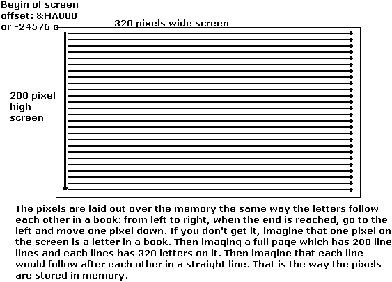
The screen (in screen 13) has 320 * 200 = 64000 pixels. Each pixel
can have a value from 0-255. Hey! This exactly the same value a byte
can have. And, it won’t surprise you: each pixel is one byte in memory.
But how you know which coordinates (x: 0-319, y: 0-199) are with which
offset(0-63999)? When you have the coordinates and you want to get the
offset, use this formula:
offset& = y * 320& + x
Then you poke or peek at that offset. Poke to set the pixel at
that offset to a certain colour, and peeking to get the colour at
that offset. Like this you can use peeking and poking instead of
psetting and pointing. When you poke a value or colour more then
255, the counting will start over again. So 256 becomes 0, 257
becomes 1, just like -1 becomes 255, -2 becomes 254…
Be sure that you use LONG integers for the offset, and a LONG
sign after the 320, to avoid an overflow error. But, of course you
can’t peek and poke to that yet, because the screen offset doesn’t
start at the starting segment of qbasic. It actually is at &HA000.
That looks weird, because it is a hex number(hex numbers have &H
before it always in qbasic). We use hex numbers just because &HA000
is easier to remember then -24576(the matching decimal integer for
the hex number &HA000). Now you set the segment to &HA000 or -24576,
you can poke to it where you want. Code:
DEF SEG = &HA000
When you’re ready with poking to the memory, always return to the normal
segment by DEF SEG (without any arguments). When you don’t do
this there may be some weird errors (screens that freeze and a bunch of other
things).
That is a useful feature of peeking and poking: it is much faster then pset and point.
But this can still be made a lot faster. We can either replace that multiply
with a lookup table with a size of 199 that multiplies every value you pass to
it with 320. Make sure that you multiply with 320& and use a long integer-type
array. An other way to do it fast, and avoid that some memory is wasted by a
lookup table, is just to access the screen in the way it is stored in memory:
row by row. You just initialise the pointer to zero, and after you plotted a
pixel, you add one to the pointer to go the next pixel. Be sure that the x
loop is the inner loop and the y the outer loop! Else it will mess up.
Here’s some code.
SCREEN 13
DEFINT A-Z
DEF SEG = &HA000
pointer& = 0
FOR y = 0 TO 199
  FOR x = 0 TO 319
    POKE pointer&, colour
    pointer& = pointer& + 1
  NEXT
NEXT
DEF SEG
Of course, the pointer is a long integer again.
There are still some faster and faster ways to get an image to the screen.
That is with a buffer. BTW, I still want to teach you something extras
about the VARSEG shit.
VARSEG and VARPTR
Do you remember the value of an integer, that was stored in memory with
the second bit representing a value 0-255 that needs to be multiplied with 256? Well,
varseg and varptr work actually the same way. Only, varseg is 16 times the pointer
instead of 256(that is because the segment is shifted 4 bits to the left, if you
understand, and care). Instead of adding 16 to the pointer, you could add one to
the segment. The same logic: instead of adding 320 to the pointer, we could add
20 to the segment. So, instead of drawing the whole screen with one long integer,
we can draw the screen with one integer, and update the segment every line. We do
this like this:
DEF SEG = &HA000 + y * 20
Then we draw like this:
FOR x = 0 TO 319
  POKE x, colour
NEXT
This is not really faster then the other ways I showed you, but it is added
for completion, and to show you how varseg and varptr relate to each other. BTW,
some programs use this, and now you know exactly what’s happening ;). It is
possible to get the multiply by 20 out, and then it is, as I believes, the fastest
way of poking to the screen. You just add a variable that increases with 20 each
time on the end of the y-loop. You don’t need a long integer anymore that makes
it slow. The code is:
SCREEN 13
DEFINT A-Z
yp = 20
FOR y = 0 TO 199
  DEF SEG = &HA000 + yp
  FOR x = 0 TO 319
    POKE x, colour
  NEXT
  yp = yp + 20
NEXT
Of course, you can replace the &HA000 segment by a buffer segment(you will
learn later how to do this). The fastest way, however, would be to write some
ASM routines. One to write to the buffer, some kind of PSET, and another to
copy the buffer to &HA000. This is not that hard to do, and well worth the effort
when you’re, for instance, making a game. It is also a fairly good practice for
your ASM coding.
Poking to a buffer
When you want to have flicker free graphics, a buffer is very useful. It
eliminates almost every flickering. The trick with a buffer is to set the segment
not to &HA000, but to the segment of a buffer. The actual buffer is just a large
array of short integers. The buffer needs to have enough memory for
- All pixel colours
- The height and width information
The size for the pixels is easily calculated by just multiplying the width of
the pic by the height of it. Then you divide by two, because we don’t use bytes but
integers, which exist out of two bytes. Then you add two, because the information
needed to put the pic to the screen is two integers. Formula:
Size = INT(width * height / 2 + .5) + 2
So, for a screen size buffer you get (320 * 200) / 2 + 2 = 32002 elements.
So, you dim an integer array with 32002 elements:
DIM buffer(32001) AS INTEGER
That actually are 32002 integers, because the counting starts at 0. So 0-32001
elements are 32002 elements ;).
Then you set the segment to the segment of the buffer:
DEF SEG = VARSEG(buffer(0))
Or, when you want to use this segment more frequently, you can first save the
segment in an integer:
buffersegment = VARSEG(buffer(0))
DEF SEG = buffersegment
But before you try this, you have to give up the width and height of the
buffer too. This is called initialising the buffer. It is needed to blit the
buffer to the screen. We do it in the following way: we set the first element
(in this example: buffer(0)) to 8 times the width. I don’t exactly know why
the width needs to be multiplied by eight, but be sure to do it, else it won’t
work. The second element is set to the height. In code:
buffer(0) = 8 * bufferwidth
buffer(1) = bufferheight
Ok, now you’ve set the segment and initialise the buffer, you’re ready to poke
to it. One thing I have to tell you about: there are easier ways to use a buffer.
With get and put. Once you have dimmed an array with enough space you can get any
portion of the screen with this command:
GET (x1, y1) – (x2, y2), buffer(0)
And put it on any position:
PUT (x, y), buffer(0), PSET
With PSET you make sure that the buffer overwrites the background. When you
don’t use it, it looks very weird. Not recommended :P.
An easier way to initialise the buffer is to simply GET the whole screen:
GET (0, 0) – (319, 199), buffer(0)
But, this copies the whole screen into your buffer, so when you want to have
a empty buffer your screen needs to be empty too ;). I told you about the
height/width manner too, because you need to know how GET/PUT work. GET
initialises the array automatically with the width and height, and PUT blits
the buffer super-fast to the screen.
You’re almost ready to use the buffer, the only thing to know is that your
pointer starts with a value(offset) of 4. This is because the first two integers
are used to save the height and width. And each integer is two bytes. So, when we
put everything together:
SCREEN 13
DEFINT A-Z
DIM buffer(32001)
buffer(0) = 320 * 8
buffer(1) = 200
pointer& = 4
FOR y = 0 TO 199
  FOR x = 0 TO 319
    POKE pointer&, RND * 255
    pointer& = pointer& + 1
  NEXT
NEXT
PUT (0, 0), buffer(0), PSET
Well, it’s not that hard, huh? And, the nicest, it gets rid of all flicker!
When your having memory problems, try using REM $DYNAMIC in your code. It gives
you more memory to use. Very handy when you use a buffer, because a buffer eats
up almost all memory. The only little downside of a buffer. But when you use dynamic
memory, with REM $DYNAMIC, you have no problems with that. One last thing, when you
have still some flicker, try this:
WAIT &H3DA, 8
WAIT &H3DA, 8, 8
Right before you PUT the buffer to the screen. That should eliminate all flicker. Bang :P.
Quick filtering
I will present a way to do very fast blurring or a fast fire filter.
You can do this by poke at the current pixel and peek at the right places:
for a blur filter, peek at the surrounding pixels, so:
- Pixel above:
PEEK(p& - 320)
- Pixel left:
PEEK(p& - 1)
- Pixel right:
PEEK(p& + 1)
- Pixel down:
PEEK(p& + 320)
Then you divide the value of all this pixels together, and poke this at
the pointer. You may need a loop from x: 1 to 318 and y: 1 to 198. This is a
bit weird coded, because the pointer needs to skip the first and last pixels
of a line. Also notice that you need to have a gradient palette to blur. Code:
SCREEN 13
DEFINT A-Z
FOR c = 0 TO 255
  OUT &H3C8, c
  OUT &H3C9, c / 255 * 63
  OUT &H3C9, c / 255 * 63
  OUT &H3C9, c / 255 * 63
NEXT
DEF SEG = &HA000
P& = 0
FOR y = 0 TO 199
  FOR x = 0 TO 319
    p& = p& + 1
    POKE p&, RND * 255
  NEXT
NEXT
DO UNTIL LEN(INKEY$)
  p& = 321
  FOR y = 1 TO 198
    FOR x = 1 TO 318
      total = PEEK(p& - 320) + PEEK(p& - 1) + PEEK(p& + 1) + PEEK(p& + 320)
      POKE p&, total \ 4
      p& = p& + 1
    NEXT
    p& = p& + 2
  NEXT
LOOP
DEF SEG
You can make a LUT for the divide by four. The size of the LUT needs to be from
0 to 4 * 255 = 1020. You can add the centre pixel too and divide by five. The size
needs to be 5 * 255 = 1275 then. This gives a slightly less, but better blur.
If you want to copy one buffer to another, you just make a 0-199 loop and swap
the segment every time in the inner loop, like I told you in ‘VARSEG and VARPTR’.
Between the PEEKing from the one buffer and POKEing to the other, you need to
save the values in a LUT, which can hold 319 integers.
If you want to know more:
Memory tutorial (© by Qbasic for All!) – Teaches you all about the memory in Qbasic(not
about using it or implemention, but just how all the commands concerning memory):
http://www.petesqbsite.com/sections/tutorials/tuts/memory.htm
Get and put tutorial by Andrew L. Ayers – All about GET and PUT.
http://www.petesqbsite.com/sections/tutorials/tutorials/getput13.txt
Extra
I actually finished this tutorial, but then I though about something that
Galleon learned me. Credits go to him.
It is another way of using a buffer, but now you write to it with Qbasic’s
graphical functions(PSET, POINT, LINE, CIRCLE, GET, PUT). I think that it is
very cool when you understand it. But, it’s gonna be a bit complicated, so don’t
worry when you don’t understand. That’s why I called this part “Extra”.
What I’m going to try to explain to you, is a way to use Qbasic’s graphical
functions with a buffer. So, when you use LINE, it draws a line to the buffer. Unfortunately,
this doesn’t work for PRINT because text uses another segment.
First, we have this idea:
We know that Qbasic build-in graphical functions writes pixels to the
screen. But we want qbasic to write to our buffer. I accidentally know
that the place where Qbasic lets its graphical functions draw, is stored
somewhere in memory. So somewhere in the memory must be standing: &HA000.
OK. Now we must translate this idea to code:
Search in the whole default segment of Qbasic (0-65535) for &HA000. When you
make &HA000 an integer, and you look up each byte, you get:
- First byte: 0
- Second byte: 160
So it is easier to make an IF into the loop:
'Scan the whole memory
FOR pointer& = 0 TO 65534
  IF PEEK(pointer&) = 0 AND PEEK(pointer& + 1) = 160 THEN
    'You’ve found &HA000, now check if it’s the right place in the memory
Now we need to check if it’s actually the right place in the memory. We do this by
messing up the place where &HA000 stood first. Then we PSET a colour at (0, 0). Then we
peek a value at segment &HA000, offset 0. If that is the colour, then it is not the right
place in memory, so we restore &HA000 at the current offset and we need to continue
searching. If it is not that colour, we save the current value of pointer&, and stop
searching:
  'We mess up the first byte(we make it 1 instead of 0)
  POKE pointer&, 1
  'Then we try if PSET still PSETs at &HA000
  PSET (0, 0), 127
  'If it does not, we have the right place
  DEF SEG = &HA000
  IF PEEK(0) = 127 THEN
    'We have a wrong place, restore pixel at (0,0), and get &HA000 back into memory
    DEF SEG
    PSET (0, 0), 0
    POKE pointer&, 0
ELSE
    'We found the right offset, so get the buffer segment into the place of &HA000, then exit from the FOR loop
    DEF SEG
    place& = pointer&
Now we need to get the segment of the buffer into the memory. But here is a little problem,
because you can only set a segment in the memory and no pointer. But we want to start the
drawing at buffer(2), because the first two elements are saved for the height and width of
the pic. We can’t increase the segment by two due to the fact that the segment is 16 times
the offset. So an offset of 1(byte) in the segment would mean 16 bytes in the pointer. Hey!
Now we can use it! We just dim our buffer a bit bigger then normal, and let the drawing
start at buffer(8), which is the 16th byte in the array. So the width is set at buffer(6)
and the height at buffer(7). Then we can PUT it to the screen with:
PUT (0, 0), buffer(6), PSET
Also, you can easily initialise it with GET again:
GET (0, 0) – (319, 199), buffer(6)
Now we need to write the segment(VARSEG(buffer(8))) into memory. The memory is
split up in bytes, we need to split up the segment in bytes. We do this by letting
the first byte be the value AND 255, and the second byte the value \ 256. Code:
Segment = VARSEG(buffer(0)) + 1
POKE pointer&, segment AND 255
POKE pointer& + 1, segment \ 256
This manner(ANDing by 255 for the first byte and integer dividing by 256 for the second) works
also fine with writing positive values to integers.
Now you’ve done all this, we’re almost finished. One important thing to know is that you can’t
PUT to the screen no more, because you PUT to the buffer. When you want to put to the screen, you
will need to restore the &HA000 segment in memory. Therefore, you need to save the pointer into a
variable. To restore the &HA000 segment:
POKE place&, 0
POKE place& + 1, 160
Then you put the pic to the screen and then you restore the segment of the buffer in memory.
It’s recommended to put this into two subs, one for initialising the buffer and finding
the &HA000 in the memory, and the other to put the buffer to the screen. Well, I will
give you the whole code with some code to test it:
Note: the SUB initialises the buffer, searches the memory for &HA000 and sets the buffer
segment in the place of &HA000.
The SUB refresh sets the segment in memory back to &HA000, blits the buffer to &HA000, then
sets the segment back.
DECLARE SUB refresh ()
DECLARE SUB initialise ()
CLS
SCREEN 13
DEFINT A-Z
DIM SHARED buffer(32007)
DIM SHARED segment, firstbyte, secondbyte
DIM SHARED place AS LONG
initialise
DO
'Use this instead of CLS:
LINE (0, 0)-(319, 199), 0, BF
'(CLS will work on &HA000 always, and we only want to clean the buffer)
FOR x& = 0 TO 10000
  PSET (RND * 319, RND * 199), RND * 255
NEXT
refresh
LOOP

SUB initialise
'Initialise the buffer, set the segment and the two bytes
buffer(6) = 320 * 8
buffer(7) = 200
segment = VARSEG(buffer(0)) + 1
firstbyte = segment AND 255
secondbyte = segment \ 256
FOR pointer& = 0 TO 65534
  IF PEEK(pointer&) = 0 AND PEEK(pointer& + 1) = 160 THEN
    'You’ve found &HA000, now check if it’s the right place in the memory
    'We mess up the first byte(we make it 1 instead of 0)
    POKE pointer&, 1
    'Then we try if PSET still PSETs at &HA000
    PSET (0, 0), 127
    'If it does not, we have the right place
    DEF SEG = &HA000
    IF PEEK(0) = 127 THEN
      'We have a wrong place, restore pixel at (0,0), and get &HA000 back into memory
      'then continue with the loop
      DEF SEG
      PSET (0, 0), 0
      POKE pointer&, 0
    ELSE
      'We found the right offset, so get the buffer segment into the place of &HA000
      'and save pointer& into place&, then exit from FOR loop
      DEF SEG
      place& = pointer&
      POKE place&, firstbyte
      POKE place& + 1, secondbyte
      EXIT FOR
    END IF
  END IF
NEXT
END SUB

SUB refresh
'Set memory to &HA000
POKE place&, 0
POKE place& + 1, 160
'Put the buffer to &HA000
PUT (0, 0), buffer(6), PSET
'Restore buffer segment into memory
POKE place&, firstbyte
POKE place& + 1, secondbyte
END SUB
Conclusion
I hope you liked this tut, and everything was clear. You may send me some feedback on
basicallybest@live.nl. BTW, thanks for reading the tut.
And also don’t bother to mail me if you don’t understand something. Also check out my site:
http://members.lycos.nl/rubynl
It’s a bit old, but I’m doing a re-organization soon.
Greets,
Codemss/RubyNL (Codemss is my new username).
Credits
Plasma for SetVideoSeg
Sphere mapping tutorial
By Codemss (RubyNL)
Introduction
Sphere mapping is a very nice trick that is used much on demos. I found
however that there are no tutorials on how to do it easily. One approach is
to use inv-sin and inv-cos operations, but I found that that way sucks. When
I was messing with some things to make a circle, I found out that it is
actually very simple. I will describe a pretty nice technique for this. I
believe that Relsoft used this technique also in Mono and disco, for both the
sphere mapping and the lenses. A little knowledge of vectors and normals would
come in handy to understand what this manner actually does, but it is not a must.
The dot product and normalizing vectors will be explained here too, but I won’t go
in any details.
Introduction to geometric equation of spheres
What? Geometric equations for spheres? What is that? Well, you remember the equation
that you may have learned on high school, for a circle:
SQR(x ^ 2 + y ^ 2) = r
R is the radius of the circle, of course. We can easily translate this to 3d:
SQR(x ^ 2 + y ^ 2 + z ^ 2) = r
When we want to so sphere mapping, we need to know the z coordinate a
point(x, y) on the sphere. We need to check if it’s on the sphere also. Now, we
can use this equation to make an equation for z.
SQR(x ^ 2 + y ^ 2 + z ^ 2) = r
					Take the square of both sides
x ^ 2 + y ^ 2 + z ^ 2 = r ^ 2
					Subtract x ^ 2 and y ^ 2 on both sides
z ^ 2 = r ^ 2 – x ^ 2 – r ^ 2
					Take the square root of both sides
z = SQR(r ^ 2 – x ^ 2 – y ^ 2)
This square root is necessary evil, so I will explain one or more ways to make a
lookup table for this later. First, we need to check if the point(x, y) is actually
on the sphere. This is very easy. You know that you can’t take a square root of a
negative number, so when the equation inside the brackets of the square root is
negative, the point cannot be on the sphere. Notice that x and y have to be in
range –r to r, not in range 0 – 2r. Code:
CLS
SCREEN 13
DEFINT A-Z
CONST r = 50
FOR y = -r TO r
  FOR x = -r TO r
    equation& = r ^ 2 - x ^ 2 - y ^ 2
    IF equation& => 0 THEN
     Z = SQR(equation&)
     PSET (x + 50, y + 50), 15
    END IF
  NEXT
NEXT
END
Colouring based on z-coordinate
I used a long integer for the equation, because it may overflow at larger radiuses.
We didn’t use the z coordinate in the colouring. We could use colouring based on the z
coordinate. BTW, the z coordinate is always positive, because we are saying: z = square root
(blabla) and square roots are always positive. When you would want the backside of the sphere,
you had to take the negative of z (–z). Now when we want to look it 3d, we simple say
colour(x, y) = zcoordinate(x, y)
BTW, we divide by the radius and multiply by 255 to get the colours into the good range. Code:
CLS
SCREEN 13
DEFINT A-Z
FOR c = 0 TO 255
  OUT &H3C8, c
  OUT &H3C9, c / 255 * 63
  OUT &H3C9, c / 255 * 63
  OUT &H3C9, c / 255 * 63
NEXT
CONST r = 50
FOR y = -r TO r
  FOR x = -r TO r
    equation& = r ^ 2 - x ^ 2 - y ^ 2
    IF equation& => 0 THEN
      Z = SQR(equation&)
      PSET (x + 50, y + 50), z / r * 255
    END IF
  NEXT
NEXT
END
In case you don’t know: the first FOR…NEXT loop is for the palette.
Ok, now this is more what we want! It looks already a bit 3d. Before going on I
got to tell you some optimizing stuff:
- Always use x * x instead of x ^ 2. This is for y, z and r the same
- Precaculate a constant that is r * r, then you can use this constant in the equation in the inner loop
- Precalculate y * y in the outer loop, instead of the inner loop
So, this would the new code for the inner loop be:
CONST r2 = r * r
FOR y = -r TO r
  y2 = y * y
  FOR x = -r TO r
    equation& = r2 - x * x - y2
    IF equation& => 0 THEN
      Z = SQR(equation&)
      PSET (x + 50, y + 50), z / r * 255
    END IF
  NEXT
NEXT
END
This is quite a bit faster, but we still can’t use this in real-time.
I will tell you: that is kinda impossible, so we have to calculate a lut.
Not that I’m explaining this now, just that you know it. I hate surprises :P.
Texture mapping
OK, now you’re ready to learn to texture the sphere! It is basically a matter
of just multiplying the x and the value by the z component of the normal. If you
don’t know what that is, don’t be scared. It is just the z coordinated divided by
the radius. So:
u = x / z * r
v = y / z * r
U and V are just texture coordinates. When we implant this into our loop, we
have to change from the geometrically right equation& => 0 to equation > 0, to
avoid dividing by zero issues. We can, instead of using a real texture, use a
XOR texture, made by easily XOR’ring the u by the v coordinate:
colour = u XOR v
I don’t give you code yet, because I’ve got more to tell you. We can also multiply
the z component of the normal by the texture to get a shaded and textured sphere. You
only have to make sure that you AND the colour from the XOR texture by 255, so for the
colour:
colour = ((u XOR v) AND 255) / r * z
If you don’t do this, the shading won’t work.
Full code is(note that I used a gradient palette again):
CLS
SCREEN 13
DEFINT A-Z
FOR c = 0 TO 255
  OUT &H3C8, c
  OUT &H3C9, c / 255 * 63
  OUT &H3C9, c / 255 * 63
  OUT &H3C9, c / 255 * 63
NEXT
CONST r = 50
CONST r2 = r * r
FOR y = -r TO r
  y2 = y * y
  FOR x = -r TO r
    equation& = r2 - x * x - y2
    IF equation& > 0 THEN
      z = SQR(equation&)
      u = x / z * r
      v = y / z * r
      PSET (x + 50, y + 50), ((u XOR v) AND 255) * z / r
    END IF
  NEXT
NEXT
END
Y ratio correction
You may have noticed that the sphere is a little too high. We have to fix
this with manipulating the y coordinate of a point. We have to divide by 5 and
multiply by 6. Then we use this y coordinate in the equation for the texture.
An easy way to do this:
...
FOR yy = -r TO r
  y = yy / 5 * 6
  y2 = y * y
  ...
  PSET (x + r, yy + r), colour
...
Like this you can fit in the code easily.
Bigger radius’
When you use a bigger radius, you may come across some problems:
- Overflow errors
- Very big, obvious and ugly aliasing on the edges
For the first issue, you can just use long integers (like I already did with
equation&). The second issue is a little more complicated. I think that the best
way for this is to do the checking just the same, but then add a constant (I call
it ‘errorfix’) to the squareroot. The constant needs to be relative to the radius.
Code:
CONST r = 100
CONST r2 = r * r
CONST somevalue = 25
CONST errorfix = (r + r / somevalue) ^ 2
...
equation& = r2 – x * x – y2
IF equation& > 0 THEN
  z = SQR(equation& + errorfix)
  ...
END IF
Notice that I’ve added a constant named somevalue. The bigger this value,
the more aliasing problems etc you got. Still, you can make it fairly big without
real problems. Don’t make it small, because the sphere mapping effect will be not
or hardly noticeable. A value between 10-200 is fine. When you use shading also,
you can better use the normal z, so without the added errorfix, for that. This
goes for the shading with the z component as for the shading with a light vector
or point (you will learn this next).
Shading with a light vector
This is a pretty neat technique that you can use to light the sphere. First
you got to define a light vector. Try a bit what looks right. I found that this one
looks good:
lx! = -1
ly! = -1
lz! = 3
Notice that I use singles, and you should do that too, because we gonna work with
values from 0-255. You could use fixed point math for this, but that would be a waste
of work, because that would be not that much faster (and we’re going to make LUT’s for
the texturing and shading anyway)
After that, you normalize this vector. What that means is that you make the vector
have a total length of 1. You do this by dividing all components of the vector by it’s
length. I quickly made a SUB for this:
SUB normalize (x!, y!, z!)
length ! = SQR(x! * x! + y! * y! + z! * z!)
x! = x! / length!
y! = y! / length!
z! = z! / length!
END SUB
In the inner loop, you take the dot product by the normal vector of the sphere. Make sure
that the normal vector is also normalized by dividing it by the radius of the sphere (because
that is the total length of the not-normalized normal vector). Code, for the dot product:
FUNCTION dot! (x1!, y1!, z1!, x2!, y2!, z2!)
dot! = x1! * x2! + y1! * y2! + z1! * z2!
END FUNCTION
Then we just multiply the dot product by 255. But if it less then 0, you should make it zero,
because we don’t want a negative colour. Here’s the final version for a lighted sphere. Play a bit
with the light vector if you want. Code:
DECLARE SUB normalize (x!, y!, z!)
DECLARE FUNCTION dot! (x1!, y1!, z1!, x2!, y2!, z2!)
CLS
SCREEN 13
DEFINT A-Z
FOR c = 0 TO 255
  OUT &H3C8, c
  OUT &H3C9, c / 255 * 63
  OUT &H3C9, c / 255 * 63
  OUT &H3C9, c / 255 * 63
NEXT
lx! = -1
ly! = -1
lz! = 3
normalize lx!, ly!, lz!

CONST r = 50
CONST r2 = r * r
FOR y = -r TO r
  y2 = y * y
  FOR x = -r TO r
    equation& = r2 - x * x - y2
    IF equation& > 0 THEN
      z = INT(SQR(equation&))
      dotp! = dot(lx!, ly!, lz!, x / r, y / r, z / r)
      IF dotp! < 0 THEN dotp! = 0
      PSET (x + 50, y + 50), dotp! * 255
    END IF
  NEXT
NEXT
END

FUNCTION dot! (x1!, y1!, z1!, x2!, y2!, z2!)
dot! = x1! * x2! + y1! * y2! + z1! * z2!
END FUNCTION

SUB normalize (x!, y!, z!)
length! = SQR(x! * x! + y! * y! + z! * z!)
x! = x! / length!
y! = y! / length!
z! = z! / length!
END SUB
I took the integer part of z, because it may be a little too big else. For
texturing this doesn’t matter, but for lightning it does, because it turns black at
the brightest points else. Well, try removing the INT if you don’t know what I mean.
Real-time rendering by using a LUT
A LUT, a lookup table, is a handy thing when you want to do real-time things that actually
can’t be done in real-time. The ‘secret’ of a lookup table is that you do precalculations
before the actual inner loop. That precalculations may take like 3 seconds, and this is MUCH
to long to do these precalculations in real-time. For sphere mapping, the first reflex for a
sphere with radius 50, would be DIM sphere(100, 100). Don’t do this. You use too much memory
and you can’t, for instance, make a sphere with radius 150, as that would get you an error.

One way to solve this is to use a LUT that is half the size of the sphere. So:
CONST r = 50
DIM sphereLUT(r, r)
Then, you need to mirror the data in the LUT if the point you want to draw is on
the right or on the bottom side of the sphere. The good thing is that you can use this
table for both the u and the v coordinates if you mirror it right.
It is also possible to save everything in one large array, but this costs some more memory.
Less memory then saving the whole sphere is used however, but still more then the other manner.
You need to check one time how many pixels are used, then DIM the LUT, and then fill the LUT.
That costs a little more time, but I believe this method is a bit faster.
A problem occurs when you try to draw the sphere, because it tries to draw a solid rectangle. For
this, you need an array of size radius, where you save every highest value on the x-axis. Then in the
inner loop you do:
FOR y = -r TO r
  FOR x = -array(y) TO array(y)
    Draw sphere here
  NEXT
NEXT
An example program is here. If you’re having problems, look it up here. This is quite old code
(I am too lazy too write this code again), so much things may be vague to you. I use a weird sphere
mapping technique there, but ignore that. Before I forget :P, here’s the code:
SCREEN 13
DEFINT A-Z
xc = 160
yc = 100
r = 100

FOR x = 0 TO 255
  OUT &H3C8, x
  OUT &H3C9, x / 255 * 63
  OUT &H3C9, x / 255 * 63
  OUT &H3C9, x / 255 * 63
NEXT

DIM array(100, 100), xwidth(100), shade(100, 100)
FOR y = 0 TO 100
  FOR x = 0 TO 100
    delta = -(x ^ 2 + y ^ 2 - r ^ 2)
    IF delta > 0 THEN
      nz! = SQR(delta) / r
      nx! = ((x) / r)
      ny! = ((y) / r)
      u = (((((nx! * (2 - nz!)) / 2) + 1) / 2) * 255)
      array(x, y) = u
      IF x > xwidth(y) THEN xwidth(y) = x
      shade(x, y) = nz! * 128
    END IF
  NEXT
NEXT

LINE (0, 0)-(319, 199), 0, BF
DEF SEG = &HA000
DO UNTIL LEN(INKEY$)
  FOR y = -100 TO 100
    yd = ABS(y)
    xw = xwidth(yd)
    offset& = (yc + y) * 320& + xc - xw
    FOR x = -xw TO xw
      xd = ABS(x)
      IF xd <= 100 AND yd <= 100 THEN
        pixel = array(xd, yd)
        u = pixel
        IF x < 0 THEN u = 255 - u
        v = array(yd, xd)
        IF y < 0 THEN v = 255 - v
        c = ((u + a) XOR (v + b)) AND 255
        c = (c * shade(xd, yd) \ 128)
        POKE offset&, c
        offset& = offset& + 1
      END IF
    NEXT
  NEXT
  a = (a + 1) AND 255
  b = (b + 1) AND 255
LOOP
DEF SEG
SLEEP
END
A lighting LUT is implemented exact the same way. But notice that when you’re shading with
a light vector, the shading cant be implemented with the first way, because you really have
to save each pixel apart. This is because the shading is non-symmetrical, so you cannot use
the array size optimization because that uses symmetry.
Other ideas
This tutorial has become a bit longer then I meant it to be, so I aint writing no more in
detail. I explained everything what I know in detail now, but I still have some other thing I
haven’t really tried myself to tell you. The first thing is about lightning. I explained the
shading with a light vector to you, but it’s also possible with a light point. For this, you
have to take the vector to the point. This is not that hard. Do this in the inner loop:
- Set the vector as (lx - sx, ly - sy, lz - sz). (Sx, sy, sz) is the sphere position and (lx, ly, lz) the light position.
- Normalize vector.
- Take the dot product of vector to the light and the normalized (divided by radius) normal.
- If the dot product is less then 0, set it to 0.
- Plot the point with colour dot! * 255.
Ready! Now about rotating. Normally, there are three rotation angles, one for each angle.
| Rotation about x-axis | Pitch | Done with adding numbers to texture coordinates. |
| Rotation about y-axis | Yaw | Done with adding numbers to texture coordinates. |
| Rotation about z-axis | Roll | Done with a rotation formula. |
Pitch and yaw can be easily implemented by adding numbers to the u and v coordinates
(texture coordinates). Of course you need to AND the texture numbers to keep them in range.
When you want to implement roll, you will need this formula:
u = (x * cos(angle)) + (y * sin(angle))
v = (y * cos(angle)) - (x * sin(angle))
Roll is so hard to implement because the u and v coordinates actually rotate. With the x
and y rotation, the x and y actually stay the same, but you just change their range by adding
something to them. The pitch and yaw we use, depends on texture sizes, but when you want to
give them up in radians, you need to convert them by diving through 2 * pi and multiplying
with texture size.
What also is very nice to do is making two LUT’s, one for the texturing and one for the
lightning, and them mix them in real-time. Then you could add for example, phong lighting to
the light LUT. It is also possible to rotate the lighting LUT, just the same way you rotate
the texture LUT.
A scroller must be to easy to implant, and you could make it transparent by not painting
the background pixels. Like that you could make more scrollers inside each other, sounds like
a nice idea...
Conclusion
I hope you liked this tut, and everything was clear. You may send me some feedback on
basicallybest@live.nl. BTW, thanks for reading the tut.
And also don’t bother to mail me if you don’t understand something. Also check out my site:
http://members.lycos.nl/rubynl
It’s a bit old, but I’m doing a re-organization soon.
Greets,
Codemss/RubyNL (Codemss is my new username).
Almost forgot:
Credits
Galleon for helping to optimize my program.
Relsoft and (especially) Biskbart for their sources.
Making a Particle Engine, Part I
Written by notthecheatr
Note: This is a beginning level tutorial written using FreeBasic - converting to QBasic, or other similar BASIC variants, should
not be very difficult, only bear in mind that this is written mainly for FreeBasic.
Another note: All source code and example programs may be downloaded in a ZIP file - the link is at the bottom of the tutorial.
Hey there, notthecheatr here writing my first tutorial. I'm going to show you
how to write a particle engine in FreeBasic. We'll start with the basics, no pun
intended, and work from the ground up. There aren't a whole lot of tutorials
on this topic (though if you Google you'll find a few), so I'm writing from a beginners
stand-point, building up over several parts to a powerful and flexible particle
engine built entirely from scratch. I think you'll enjoy it, maybe you'll even learn
something from it.
Right, so the first thing we need to understand is what a particle engine is
and why you'd want to make or use one. A particle engine is essentially the
structures for organizing and the code for updating particles. In other words,
you'd have a few data structures that tell how to create and initialize these particles,
then you'd have the code to move the particles around in a predefined way. The
result? Well, when you have a couple thousand particles on the screen, the result
generally looks pretty cool. In fact, particle engines can be used to create decently
realistic explosions and fireworks, flames, smoke, water fountains, sprinklers, jets,
rain, snow, and much more. Probably if you're writing an RPG you'll want to do some
of the spell animations this way. So in short, the reasons for writing a particle engine
are many - but to me, the most important one is that it's a lot of fun. It's not hard to
do, and the return (really cool effects) is worth it. So let's begin!
OK, so now we know what a particle engine is, how shall we go about implementing it? Well a particle system generally has two basic parts: the emitter,
and the particles. You might have more parts, but these form the foundation. The emitter emits the particles, and keeps track of them. In my system, the emitter is responsible for updating the particles and eventually drawing them (actually, each particle draws itself, but that'll come later...) Thus, you can think of the emitter as a kind of gun that shoots out little tiny dots. Note that these dots can move in a variety
of ways - they won't necessarily look like bullets, they might look like snowflakes. Or rain, smoke, fire - or anything else you can think of that is made of particles.
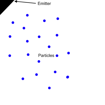
OK, so we want a structure for the emitter and a structure for each individual
particle. Now if we're going to have thousands of particles in memory then it would
probably be wise to keep the variables in the particle structure down. Thus, we'll
try to put as many variables in the emitter as we can, since there usually won't be
thousands of those.
So what is a particle? Essentially an object. In physics, your average object
has two essential characteristics. These characteristics are the basis for our particle,
and in fact without these characteristics our particle would be nothing. We will add
other things to our particle type later, to make it do more interesting things, but
for the moment we'll focus on the most important thing. Every particle has to know
where it is now, and where it's going (how fast in each direction, to be exact). In other words, you need to keep track of it's position (x, y, z) and velocity (vx, vy, vz):

Note: Throughout this tutorial I develop a particle engine that keeps
track of the z coordinate, though I personally stick to 2d particles. If you don't need a 3d particle, you may also leave out z and any code relating to it. Otherwise, you may do as I do and simply ignore the z component when you don't need it. Either way is fine, updating a third component doesn't take particularly long to do.
Now our emitter also needs to start out at some location, or else all our particles
will come out of the top-left corner of the screen, which is not always what we want.
The emitter also needs to know how many particles it may create maximum, how
many particles it is keeping track of NOW, and what the rate of emission is. We should also have some flags that allow us to quickly turn the emitter on or off. Once
again, we'll be adding tons of things to this, but for now our two structures look like this:
  #Define FBPE_FLAGS_EMITTING 1
  #Define FBPE_FLAGS_VISIBLE     2
  #Define FBPE_FLAGS_MOVING    4

  Type FBPE_Particle
    As Single x, y, z
    As Single vx, vy, vz

    'r = radius.  Used mainly to keep track of whether the particle has been initialized
    'yet, or in collision detection.
    As Integer r
  End Type

  Type FBPE_Particle_Emitter

    As Integer location_x, location_y, location_z

    As Integer maxparticles, numparticles, emissionrate

    As Byte emitterflags

    As FBPE_Particle Ptr particles

  End Type
Notice that particle ptr! It let's us use a variable number of particles in each emitter, so you can have 20 particles or 20,000 from two emitters with the same UDT. That means we'll need to allocate and deallocate space. This is very simple. To make it blazing fast, we'll allocate everything at the beginning, when we initialize the emitter, and deallocate everything when we close it. No need to reallocate when we create new particles, for example. Thus, we start out with this:
  Sub FBPE_Init_Emitter (emitter As FBPE_Particle_Emitter, mparticles As Integer, prate As Integer)
  Dim As Integer i

    emitter.maxparticles = mparticles
    emitter.emissionrate = prate
    emitter.particles = Allocate(mparticles*SizeOf(FBPE_Particle))
    'Set each particle to be uninitialized
    For i = 0 to mparticles-1
      emitter.particles[i].r = 0
    Next i
  End Sub
OK, so our emitter is initialized... let's add some code for making it start:
  Sub FBPE_Start_Emitter (emitter As FBPE_Particle_Emitter)
    emitter.emitterflags = (FBPE_FLAGS_EMITTING Or FBPE_FLAGS_VISIBLE Or FBPE_FLAGS_MOVING)
  End Sub

  Sub FBPE_Pause_Emitter (emitter As FBPE_Particle_Emitter)
    'Turn off all flags except visibility
    emitter.emitterflags = emitter.emitterflags And FBPE_FLAGS_VISIBLE
  End Sub

  Sub FBPE_ToggleVisibility_Emitter (emitter As FBPE_Particle_Emitter)
    'Toggle visible flag
    emitter.emitterflags = emitter.emitterflags Xor FBPE_FLAGS_VISIBLE
  End Sub

  Sub FBPE_Close_Emitter (emitter As FBPE_Particle_Emitter)
    emitter.emitterflags = 0
    emitter.numparticles = 0
    DeAllocate(emitter.particles)
  End Sub
Now our emitter does: precisely nothing. We need an update function. What
the update function does is move particles around on the screen. It's usually used in
a loop, so it'll need to be fairly efficient. It also needs to work. Note that we won't display our particles using this update function - we'll only move them around. Displaying the particles is done separately, so eventually the user will be able
to choose how they're drawn and when.
  Sub FBPE_Update_Emitter (emitter As FBPE_Particle_Emitter)
  Dim As Integer i

    'If we're still emitting...
    If (emitter.emitterflags Or FBPE_FLAGS_EMITTING) <> 0 Then
      'Emit the number of particles we're supposed to emit...
      emitter.numparticles += emitter.emissionrate

      'If we've emitted as many as we can, turn the emitter off.
      If emitter.numparticles > emitter.maxparticles Then
        emitter.numparticles = emitter.maxparticles
        emitter.emitterflags = emitter.emitterflags And (Not FBPE_FLAGS_EMITTING)
      End If
    End If

    If (emitter.emitterflags Or FBPE_FLAGS_MOVING) <> 0 Then
      For i = 0 to emitter.numparticles-i
        'If the particle has not yet been initialized...
        If emitter.particles[i].r = 0 Then
          emitter.particles[i].x = emitter.location_x
          emitter.particles[i].y = emitter.location_y
          emitter.particles[i].z = emitter.location_z
          emitter.particles[i].vx = 1
          emitter.particles[i].vy = 1
          emitter.particles[i].vz = 1
          emitter.particles[i].r = 1
        Else
          'Move the particles, with a small amount of randomness built in
          emitter.particles[i].x += emitter.particles[i].vx + (Rnd*2) - 1
          emitter.particles[i].y += emitter.particles[i].vy + (Rnd*2) - 1
          emitter.particles[i].z += emitter.particles[i].vz + (Rnd*2) - 1
        End If
      Next i
    End If
  End Sub
OK, now we have everything but drawing. Our particles are just numbers in
memory up until now. Let's draw them on the screen! Once again we'll be making this far more flexible, but for now, you can draw your particles as single
dots - or circles, or squares if you like, but keep it simple.
  Sub FBPE_Draw_Emitter (emitter As FBPE_Particle_Emitter)
  Dim As Integer i

    If (emitter.emitterflags Or FBPE_FLAGS_VISIBLE) = 0 Then Exit Sub
    For i = 0 to emitter.numparticles-i
      PSet(emitter.particles[i].x, emitter.particles[i].y), &hffffff
    Next i
  End Sub
Now if you haven't typed this all in, do so or else download the first ZIP file
below. Either way, you should compile the following test program to see how
it looks:
''
''
''FB Particle Engine - Test Program 1-A
''
''
#Include "fbgfx.bi"
Using FB

'Change this if you named it something different
#Include "fb_particle_engine.bi"

Dim As FBPE_Particle_Emitter myemitter

Screen 20, 32, 2, 1
ScreenSet 1, 0

Randomize Timer

FBPE_Init_Emitter(myemitter, 10000, 10)

FBPE_Start_Emitter(myemitter)

Do
  FBPE_Update_Emitter(myemitter)
  Cls
  FBPE_Draw_Emitter(myemitter)
  ScreenCopy
Loop Until MultiKey(SC_ESCAPE)

Sleep

Well it doesn't do a whole lot, but it already looks nice. But there are some things
we can do to improve it. Let's give the particles an optional life time. Particles may
die - or may be reincarnated, too.
#Define FBPE_LIFE_IMMORTAL            0
#Define FBPE_LIFE_DEATH                   1
#Define FBPE_LIFE_REINCARNATION  2

Type FBPE_Particle
...
  As Integer life
...
End Type

Type FBPE_Particle_Emitter
...
  As Integer initial_life
  As Byte life_behaviour
  As Integer deadparticles
...
End Type
And we'll have to modify the update Sub a bit:
Sub FBPE_Update_Emitter (emitter As FBPE_Particle_Emitter)
Dim As Integer i

  'If all particles are dead, then skip everything else
  If emitter.deadparticles = emitter.maxparticles Then Exit Sub

  'If we're still emitting...
  If (emitter.emitterflags Or FBPE_FLAGS_EMITTING) <> 0 Then
    'Emit the number of particles we're supposed to emit...
    emitter.numparticles += emitter.emissionrate

    'If we've emitted as many as we can, turn the emitter off.
    If emitter.numparticles > emitter.maxparticles Then
      emitter.numparticles = emitter.maxparticles
      emitter.emitterflags = emitter.emitterflags And (Not FBPE_FLAGS_EMITTING)
    End If
  End If

  If emitter.life_behaviour <> 0 Then
    For i = 0 to emitter.numparticles-1
      emitter.particles[i].life -= 1
      If emitter.particles[i].life = 0 Then
        If emitter.life_behaviour = FBPE_LIFE_REINCARNATION Then
          'Set particle to be re-initialized
          emitter.particles[i].r = 0
          emitter.particles[i].life = emitter.initial_life
        Elseif emitter.life_behaviour = FBPE_LIFE_DEATH
          emitter.deadparticles += 1
          If emitter.deadparticles = emitter.maxparticles Then Exit Sub
        End If
      End If
    Next i
  End If

  If (emitter.emitterflags Or FBPE_FLAGS_MOVING) <> 0 Then
    For i = 0 To emitter.numparticles-1
      'If the particle has not yet been initialized...
      If emitter.particles[i].r = 0 Then
        emitter.particles[i].x = emitter.location_x
        emitter.particles[i].y = emitter.location_y
        emitter.particles[i].z = emitter.location_z
        emitter.particles[i].vx = 1
        emitter.particles[i].vy = 1
        emitter.particles[i].vz = 1
        emitter.particles[i].r = 1
        emitter.particles[i].life = emitter.initial_life
      Else
        'Move the particles, with a small amount of randomness built in
        emitter.particles[i].x += emitter.particles[i].vx + (Rnd*2) - 1
        emitter.particles[i].y += emitter.particles[i].vy + (Rnd*2) - 1
        emitter.particles[i].z += emitter.particles[i].vz + (Rnd*2) - 1
      End If
    Next i
  End If
End Sub
We also need to change the drawing Sub a bit so it doesn't draw dead particles:
Sub FBPE_Draw_Emitter (emitter As FBPE_Particle_Emitter)
Dim As Integer i

  If (emitter.emitterflags Or FBPE_FLAGS_VISIBLE) = 0 Then Exit Sub
  For i = 0 To emitter.numparticles-i
   If emitter.particles[i].life <> 0 Or emitter.life_behaviour = FBPE_LIFE_IMMORTAL Then PSet(emitter.particles[i].x, emitter.particles[i].y), &hffffff
  Next i
End Sub
The result can be seen by adding the following lines to the test program:
myemitter.life_behaviour = 2
myemitter.initial_life = 100
Add these before the main loop (after the call to FBPE_Init_Emitter) and
watch the result! Particles now dissappear after a time - it looks a bit odd,
but quite a nice effect I think. The number of particles that dissappear at a time
are dependent on the emission rate, since they are all initialized with the same
amount of health; how soon they dissappear is determined by the initial_life
given to the particles. You'll probably choose these based on the kind of effect
you want to produce. By the way, in FBPE_LIFE_REINCARNATION, your program
will run forever. In FBPE_LIFE_IMMORTAL, it will run forever but eventually the
particles will run off-screen. In FBPE_LIFE_DEATH, it will run forever but eventually all the particles will be dead and you'll be looking at a blank screen. If you use
either of the latter, you may want to add code to check when they run out, so your user isn't left staring at empty space, wondering what to do next - of course,
there'll be other ways of solving that problem, coming up in later parts.
Well I hope you've enjoyed it, this has been lots of fun for me, but there's much to do still. We want to be able to send the particles in random directions, for explosion-like effects, to control the way the particles are drawn, and much more. You'll probably want gravity, you may want the particles to bounce off the walls, you might like some wind effects, and many other things. In it's current state, our particle engine is very simple and very limited. In Part II of this series I'll show you how to take it a step further, add some very useful details to it. Later, we'll work on the interface, adding a high-level layer so you can generate common effects like smoke or explosions without typing a whole lot of code. Get ready for Part II!
Contact:
TheMysteriousStrangerFromMars@yahoo.com
(or)
notthecheatr@nerdshack.com
http://notthecheatr.deviantart.com/
(and on the Official FreeBasic Forum my username is notthecheatr.)
Downloads:
fbpe_tutorial1.zip (49k)
QBE Helper and You
By Luther Ramsey (Imortis Inglorian)
Welcome to the wonderful world of QBE Helper. I will be your ruggedly handsome guide. There will be many hardships along the way. Many times you, or even I, may wet yourself in terror. Prepare for a thrill ride the likes of which has never been seen before and will never be seen again.
Okay… Maybe Not…
QBE Helper IS however a rather easy to use tool for formatting QBE articles and tutorials. As a matter of fact, I’m using it right now. It make all the tedious work of typing in the html codes as easy as clicking a button. I am here to give you an in depth walkthrough for using this helpful tool.
Getting Started
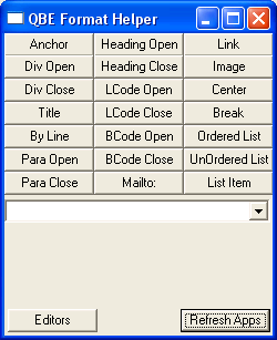
This is what the program looks like when you open it. It may look a little overwhelming, but it’s really quite simple.
Each of the top buttons represents an html tag that is commonly used in the process of formatting QBE articles of all types. Below that is a dropdown box that contains the editor programs that are currently open. At the very bottom of the window is a button to refresh the list of open editors, and a button that leads to a dialog that allows you to add to the list of editor programs.
The Editors Dialog
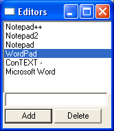
This is the editor dialog. When the program is first run, you will have Notepad++, Notepad 2, Notepad, and ConTEXT in this list. The editor is what ever you like to use to write your articles. It can be any program that can accept information from the Windows Clipboard. (Sorry DOS people. You may be able to use this from a console window, but I haven’t tried.) The Editors list contains a block of text that you can see in the title bar of the editors you use. It only has to be part of the text, not all of it. If, for instance, you wanted to use OpenOffice.org Writer, you would add this to the list:
In order to add this to the list, simply type the above into the text box on the Editors dialog, then hit enter, or click the Add button. That is all it takes.
Want to delete one from the list? If, say, you had to tweak an editor listing to get it just right, or if you want to remove an editor from the list that you never use, just highlight the item on the list that you want to get rid of and click the Delete button.
A note about ConTEXT. As you can see, the listing for ConTEXT is “ConTEXT –“. The reason for this is that ConTEXT actually makes an invisible window with the title “ConTEXT”. QBE Helper will work with either entry, but this makes the combo box much cleaner. Some programs may require this kind of hack to make them work cleanly.
Once you have added the editor of your choice to the list, just click the close button in the top right corner of the Editors dialog.
Now On To The Good Stuff
Once you are back to the main window, click the Refresh Apps button at the bottom of the window. This will look for all open windows that contain text from the list, and load them into the combo box. Then you click the combo box and select the editor window you wish to use.
Now it is time for a brief description of each of the tag buttons:
- Anchor - needed by the editors. You won’t use it much.
- Div Open/Div Close - These tags defined the open and close of your article.
- Title - this is the tag that contains the title of the article.
- By Line - this is the “Written By” tag. Just put in the author’s name.
- Para Open/Para Close - these tags go at the beginning and end of every paragraph
- Heading Open/Heading Close - these are for the minor headings at you may have in you article.
- LCode Open/LCode Close - these tags enclose any inline code. As in code that is in the paragraph, not in it’s own block.
- BCode Open/BCode Close - same as above but for blocks of code. As in code all by itself, not in a paragraph.
- Mailto: - a mailto tag, for adding an email address to the article.
- Link - a tag to include a web addresses in the article.
- Image - a tag to insert an image into your article.
- Center - a set of tags that will center anything between them
- Break - a tag for a line break
- Ordered List - this tag represent a numbered list
- UnOrdered List - this tag represents a bulleted list
- List Item - anything between these tags (and between one of the two sets of tags above) will be an item in the list.
How To Use It
All you do to put a tag into the editor is click the button that corresponds to it. This will copy the tag into the Windows Clipboard, then paste it into the editor you have chosen from the dropdown box. Simple, yes?
Example Outline
Your article will look similar to this:
Anchor
Div Open
Title
By Line
--Repeat block as often as needed
Heading Open  (Name of Article) Heading Close
Para Open (content)
(content)LCode Open (one line of code) LCode Close
Link
Center(Image)
Mailto:
Para Close

BCode Open
(preformatted code)
BCode Close

OrderedList(List Item, List Item, etc…)
UnOrderedList(list Item, List Item, etc…)
--

Div Close
Break
Break
This is of course just psudo-code. It represents the general outline of an article. Every thing between the two -- sets in the above block is variable. They can go in any order you like. You don’t have to use all tags like I have here. You can use what ever is needed. But everything else should fall into that exact outline.
Anchor
Div Open
Title
By Line
--
(everything here is up to you)
--
Div Close
Break
Break
Note that this makes editing an article a lot less time consuming, but it will not do it for you. A healthy knowledge of HTML is a plus when editing your articles.
Conclusion
Way back when( read: last issue), someone asked if we had an automated editing tool for QBE. We didn’t then, and we still don’t now. Many articles need to be edited by a human to make them come out nice and pretty for QBE.
I wrote this tool because I was tired of having to type all the tags over and over again. I will probably update the program a few times to add new tags (already thinking about a BOLD tag), or to fix errors. If anyone has feature requests, you can send them to QBExpress@gmail.com. I will personally respond to and reject each and every suggestion. Because I’m a dick like that… Not really. I want this program to be the be-all-end-all for QBE formatting needs.
Floormapping/Mode7 tutorial
By Codemss
Introduction
Floor mapping is a nice effect that can be used both in a demo
or a game. I spend quite a long time to search for tutorials on
this subject. I didn’t find any good tutorials. It’s also called
mode7 sometimes because it is used much on the old Super Nintendo.
This was done using a hardware device that was called Mode 7.
Anyway, because the computer hasn’t such a device, you will have
to do it in software mode. That may be a little bit slower, but
we have also more control about the program.
In know that Eclipzer has a good tutorial on floor mapping, but
that one doesn’t cover things as rotating. And I will :P. This
tutorial uses much trigonometry such as SIN and COS. Since I
couldn’t find any documentation , I tried to do it myself. My
first attempt didn’t work at all, due to a little fact that
I forgot. But my second attempt worked great, and, after some
optimizations, I runned on a high frame rate. Enough, let’s start.
In this tutorial you will need some knowledge of SIN and COS and how
angles with SIN and COS work. Some algebra knowledge is useful but not
necessary.
Theory
Because it is necessary, I will write about some theory first.
I use a 90 degree field of view (FOV). I call the angle where we
are viewing to ‘t’. The FOV lies between t – 45 degrees and t + 45
degrees. If we define out viewing system well, then we can say: 45
degrees = 160 pixels. Therefore, we have to make sure that have a
angle system of 1280 degrees. To do that we, have to multiply any
angle in our new angle system by 1 / 1280 * 2 * pi. Because two pi
is 360 degrees in radians (if you don’t know what the heck I’m talking
about, never mind ;), just use it). So we can make a const from this,
I cal it ‘mul’:
CONST pi = 22 / 7
CONST mul = 1 / 1280 * 2 * pi
I used 22 / 7 as alternative to pi, because constants can use
ATN(1) * 4, which is a better way to calculate pi. Now when we
have this clear, I will display what we have now in a picture:
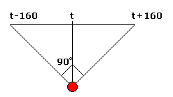
Because we can’t use a formula for each pixel, you have to
interpolate. There are two ways to interpolate, but I use only one.
That is horizontal interpolation. I will explain it with a picture:
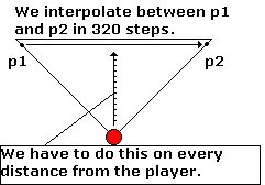
It may not be so obvious in the picture, but you need to calculate
p1 and p2 again for every distance. We take one point p1 on the left
axis(which is on angle t - 160) and a point p2 on the right axis
(on angle t + 160). We can pick this points with COS and SIN:
p1u = COS((t - 160) * mul) * distance
p1v = SIN((t - 160) * mul) * distance
p2u = COS((t + 159) * mul) * distance
p2v = SIN((t + 159) * mul) * distance
Then we interpolate between that points. We have to check this on every distance.
Well, that is actually not right. We don’t have to loop through every distance, but only
the ones where a ray intersects the floor. This is what I’ve done wrong in my first attempt
to code a mode 7 demo. Now I know at which distances to check. When we assume a player of
‘h’ pixels height, that is ‘d’ pixels between the projection screen:
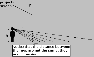
You have to check where every ray intersects the floor. This can be done
by setting up an equation. This is the same equation that Eclipzer uses for
the v solving in his floor mapping tutorial. We first calculate how much
the ray goes down in d pixels, then with that we can calculate how far the
ray goes before it intersects the floor.
- The ray goes down h – y pixels when it travels d pixels into the depth (z-axis).
- We say: Every d pixels, the ray goes down h – y pixels, so we can set up a ratio for the travelled distance / distance that the ray has travelled downwards. This ratio is: d / h - y. When we want to know how much our ray travels into depth, we need to multiply this ratio by h. Because it starts at h, we want to know when the ray travelled h pixels downwards from his starting point at y = h.
- We have now the formula: distance = d / (h - y) * h. Division by zero is impossible, so h - y can not be zero. This means that y can NEVER equal h.
- This would mean that h has to be more then 199 or less then zero (for screen 13). But there is another solution. You don’t have to render the whole screen. We can simply start at h + 1 and then go on until 199. You can also try to add more then one to avoid the worst aliasing problems, for example h + 5 or so. Or we can simply check if y = h, and if it’s so, don’t render that scanline.
A good value for both d and h is 100, but experiment a bit with these, so
that you know what effects appear when you choose bigger or smaller values
for d or h.
Now we need on which distance to check, we only have to interpolate between
the two points. I like to make a LUT for the distance of the rays. To make a
LUT, I use this code:
DIM length(h + 1 TO 199)
FOR y = h + 1 TO 199
  length(y) = (h - y) / d * h
NEXT
When I write (the important part of) the whole procedure in code:
REM Set up mul constant
CONST pi = 22 / 7
CONST mul = 1 / 1280 * 2 * pi

CONST d = 100
CONST h = 100

FOR y = h + 1 TO 199
  REM Take points p1 and p2
  p1u = (COS((t - 160) * mul) * length(y))
  p1v = (SIN((t - 160) * mul) * length(y))
  p2u = (COS((t + 159) * mul) * length(y))
  p2v = (SIN((t + 159) * mul) * length(y))
  REM In the x-loop, interpolate from p1 to p2, and draw points
NEXT
I used the same LUT as I made above. Since the interpolating is quite simple, I won’t
explain that in detail, but I have a very good trick for you. Use fixed point math with
integers. Use as scale value 512. This crashes when you the program in the IDE, but runs
so much faster when you compile it! I got it running like ten times faster then with
floating point! If you don’t know what fixed point math is, search some tutorial on
it. This one is very good (scroll down to the bottom part).
Example program
This is a floormapping example that I’ve made. I think it isn’t optimized
that much, but it runs very fast like this. I was first using long integers,
but I found out that normal integers were like 10 times faster, so I decided
to use those. The program won’t run in the IDE due an overflow error. You don’t
have this in the compiled program. If you want to run it in the IDE, I’ve made
a DEFLNG A-Z line, which makes all undefined variables log integers. It is
commented now, but when you make the DEFINT A-Z a comment (place ‘ or REM before it),
and uncomment DEFLNG A-Z (remove the ‘), it runs fine (but very slow). I made a LUT
for the distance of the rays, because the height stays the same.
DECLARE SUB ffix ()
CLS
SCREEN 13

REM Comment this line if you want to run in the IDE
DEFINT A-Z

REM And uncomment this line
'DEFLNG A-Z

REM Remove this if you have troubles with it. It speed s up floating point math.
ffix

FOR c = 0 TO 255
  OUT &H3C8, c
  OUT &H3C9, c / 255 * 63
  OUT &H3C9, c / 255 * 63
  OUT &H3C9, c / 255 * 63
NEXT
COLOR 255

DIM tex(127, 127)
FOR x = 0 TO 127
  FOR y = 0 TO 127
    tex(x, y) = 255 - SQR((x - 63.5) ^ 2 + (y - 63.5) ^ 2) / 63 * 255
    IF tex(x, y) < 0 THEN tex(x, y) = 0
  NEXT
NEXT


CONST d = 100
CONST h = 100

CONST scale = 512
DIM length(105 TO 199)
FOR y = 105 TO 199
  length(y) = d * h \ (h - y)
NEXT

CONST mul = 1 / 1280 * 44 / 7
t1! = TIMER
FOR t = 0 TO 1280
yp = 2200
FOR y = 105 TO 199
  DEF SEG = &HA000 + yp
  yp = yp + 20
  p1u = (COS((t - 160) * mul) * length(y))
  p1v = (SIN((t - 160) * mul) * length(y))
  p2u = (COS((t + 159) * mul) * length(y))
  p2v = (SIN((t + 159) * mul) * length(y))
  tu = p1u * scale
  uadd = (p2u - p1u) / 320 * scale
  tv = p1v * scale
  vadd = (p2v - p1v) / 320 * scale
  FOR x = 0 TO 319
    u = (tu \ scale + t) AND 127
    v = (tv \ scale + t) AND 127
    POKE x, tex(u, v)
    tu = tu + uadd
    tv = tv + vadd
  NEXT
NEXT
IF INKEY$ <> "" THEN END
NEXT
t2! = TIMER
DEF SEG
PRINT 1280 / (t2! - t1!)
SLEEP
END
Conclusion
I hoped you like this tutorial and everything was clear. I could explain
some more on interpolation but most programmers know how to do that and there
are very good tutorials for it available. If you’re really having troubles
with it, you may want to use my source, for everything that you don’t understand.
That is good, as long as you don’t directly copy anything around it.
You might want to try some other things, such as changing height of the player and
looking up and down. I don’t know how you can look up and down, but when (I can better say: ‘if’)
I find out how to do that, I will write another tutorial.
I have to say thanks to Eclipzer and Relsoft who got me interested in floormapping
and Eclipzer also for helping me with it.
Greets,
Codemss
Angles in 2D environment and artificial smarts based on them - Part II
Written by Lachie Dazdarian (Semptember, 2007)
Introduction
Ok then. In the previous edition of this tutorial we stopped after creating an artificial smart algorithm which controlled multiple objects that followed around the screen an object controlled by the user. This was happening in a top-down 360° rotating environment, Star Control style.
What I promised last time to do is to show you how to implement basic scrolling (among other things) to this simple educational engine. So let's get busy!
Part One
Now how does one implement scrolling? Well, relatively easy, especially in our case as we don't feature tiled background or something like that only moving objects. Scrolling is simply implemented by deducting cameraX from all x coordinates used to draw our objects with drawing primitives, and cameraY from all y coordinates. cameraX being a variable that flags the X position of the camera and cameraY being a variable that flags the Y position of the camera (both setting the upper-left corner of the camera). Just observe this code snippet:
LINE (mainx-cameraX, mainy-cameraY)-(mainx-cameraX+sin(anglerad)*20,mainy-cameraY-cos(anglerad)*20), RGB(200, 0, 0)
CIRCLE (mainx-cameraX, mainy-cameraY), 3, RGB(200, 0, 0)
Now what have we accomplished with that? Well nothing if cameraX and cameraY are 0 and/or don't change in the program. But if we "tell" the camera to lock onto the player's object, we'll get the desired result. The code that does this is as follows:
cameraX = mainx - screenmidx
cameraY = mainy - screenmidy
Where screenmidx is the half width of the screen, while screenmidy is the half height of the screen, both of which we need to set (declare) before. Why do we need to use these variables? Allow me illustrate the entire problem with a nice...illustration.
 Picture 1
As you see the camera is the size of the screen, meanining, it captures from (cameraX, cameraY) to (cameraX + screenwidth, cameraY + screenheight). Everything within this area will be visible. How come? Let's imagine that player's position is (2200, 3000). When will player's object be visible on the screen? When cameraX < 2200 and camerax + screenwidth > 2200, and when cameraY < 3000 and cameraY + screenheight > 3000. For example, if the screen resolution is 640*480 and camera position is (2000, 2700), it will "capture" from (2000, 2700) to (2640, 3180). The player's object will be drawn on (mainx - cameraX, mainy - cameraY) or (2200-2000, 3000-2700), which is (200,300), fully inside the visible screen. And that's the "trick" of scrolling in its essence.
In more graphics intensive games it is recommended you skip drawing of objects inside the map that are off the camera view, meaning in situations when object.x – camerax or object.y – cameray are less than 0 or above screenwidth/screenheight. You can do that with few simple IF clauses.
When telling the camera to lock onto an object and keep it in the center of the screen we need to use screenmidx and screenmidy because the CENTER of the camera is in (cameraX + screenmidx, cameraY + screenmid). In some situations you might have different requirements and might prefer camera not always centering the player's object. A somewhat different story is camera following (tracking) the player's or any other object (moving with slower speed than the tracked object), or moving using some path set with a script. Later on that.
I recommend putting these constants on the beginning of your program:
const screenwidth = 640
const screenheight = 480
const screenmidx = screenwidth/2
const screenmidy = screenheight/2
Where screenwidth and screenheight will correspond with the chosen screen resolution. After that you can simply set the screen resolution with:
SCREENRES screenwidth, screenheight, 32, 2, GFX_FULLSCREEN
cameraX and cameraY need to be declared as SHARED variables. Also, you need to declare two more variables, MapXMax and MapYMax, representing the size of the playfield (vertically and horizontally). In the following version of the engine I've set the player's starting position to (1000, 1000), playfield size to 2000*2000 (MapXMax = 2000; MapYMax = 2000), and randomized the computer controlled objects somewhere in the middle of the playfield (around the starting position of the player).
To keep the camera within the playfield we need to limit its movement. After...
cameraX = mainx - screenmidx
cameraY = mainy - screenmidy
...we need to place the following code:
IF cameraX < 0 THEN cameraX = 0
IF cameraY < 0 THEN cameraY = 0
IF cameraX > MapXMax - screenwidth THEN cameraX = MapXMax - screenwidth
IF cameraY > MapYMax - screenheight THEN cameraY = MapYMax - screenheight
The first two lines should be clear as cameraX and cameraY flag the upper-left corner of the very camera. The second two lines keep the camera not going off of the right and bottom edge of the map. If you observe picture 1 once more, everything should be clear. Since the bottom-right corner of the map is on (cameraX + screenwidth, cameraY + screenheight) this very coordinate must never cross the map edge (determined with MapXMax and MapYMax). screenwidth and screenwidth are placed on the right side of the two equations as we are reseting cameraX and cameraY, while MapXMax and MapYMax are always constant.
The only other piece of code I added is the one that draws the map edges so you can more easily visualize where the playfield ends. They are nothing but lines drawn around the map borders. This is the code:
LINE (MapXMax-1-camerax, MapYMax-1-cameray)-(0-camerax,MapYMax-1-cameray), RGB(255,255,255)
LINE (MapXMax-1-camerax, 0-cameray)-(MapXMax-1-camerax,MapYMax-1-cameray), RGB(255,255,255)
LINE (0-camerax, 0-cameray)-(MapXMax-1-camerax,0-cameray), RGB(255,255,255)
LINE (0-camerax, MapYMax-1-cameray)-(0-camerax,0-cameray), RGB(255,255,255)
Which I placed above the DrawProjectiles call. Once more, everywhere where LINE and DRAW statements were used to draw objects that appear INSIDE the playfield x and y coordinates were deducted by cameraX and cameraY.
The altered source code: codever3.txt
What about different camera movement? I'll show you how to implement "dragging camera" effect, where the camera moves with slower speed that the object it is tracking. For this you need to declare the following variables with SINGLE precision, and change cameraX and cameraY to same.
DIM SHARED AS SINGLE cameraX, cameraY
DIM SHARED AS SINGLE camera_xinertia, camera_yinertia
DIM SHARED AS SINGLE camera_acceleration, camera_maxinertia
DIM SHARED AS SINGLE Friction
How will the camera move in this case? With inertia! When, for example, the object that the camera is following is right from the camera, camera's X inertia will increase by camera's acceleration. In each loop the absolute value of camera's inertia will decrease (so it would stop when there is no movement) as the result of emulated friction, so the value of Friction needs to be less that camera_acceleration. Both x and y inertia mustn't become higher in absolute value than the maximum camera's inertia as the camera wouldn't move too fast and appear bouncy. This means that inertia (in both dimensions) will span from - max inertia to + max inertia.
I picked the following camera values, but you can play with them to get different results (put this with other variable initiations):
camera_maxinertia = 3
camera_acceleration = 0.4
Friction = 0.2
To move the camera in this manner replace...
cameraX = mainx - screenmidx
cameraY = mainy - screenmidy
..with:
' Update camera. Increase camera's X or Y inertia according to the
' position of the player's object.
IF cameraX < mainx - screenmidx THEN camera_xinertia = camera_xinertia + camera_acceleration
IF cameraX > mainx - screenmidx THEN camera_xinertia = camera_xinertia - camera_acceleration
IF cameraY < mainy - screenmidy THEN camera_yinertia = camera_yinertia + camera_acceleration
IF cameraY > mainy - screenmidy THEN camera_yinertia = camera_yinertia - camera_acceleration

' Keep the x or y inertia under maximum inertia value.
IF camera_xinertia > camera_maxinertia THEN camera_xinertia = camera_xinertia - camera_acceleration
IF camera_xinertia < -camera_maxinertia THEN camera_xinertia = camera_xinertia + camera_acceleration
IF camera_yinertia > camera_maxinertia THEN camera_yinertia = camera_yinertia - camera_acceleration
IF camera_yinertia < -camera_maxinertia THEN camera_yinertia = camera_yinertia + camera_acceleration

' Reduce camera's inertia by Friction.
IF camera_xinertia <> 0 and camera_xinertia > 0 THEN camera_xinertia = camera_xinertia - Friction
IF camera_xinertia <> 0 and camera_xinertia < 0 THEN camera_xinertia = camera_xinertia + Friction
IF camera_yinertia <> 0 and camera_yinertia > 0 THEN camera_yinertia = camera_yinertia - Friction
IF camera_yinertia <> 0 and camera_yinertia < 0 THEN camera_yinertia = camera_yinertia + Friction

' Move the camera according to current inertia.
cameraX = cameraX + camera_xinertia
cameraY = cameraY + camera_yinertia
The code is pretty much self-explanatory. Note how the camera is actually moved (last two lines of code).
In the continuation of this text I'll use the original "lock onto target" camera movement.
So now after we implemented scrolling and set the playfield size we should add few more constraints to the player's and computer controlled objects, not allowing them to pass the map edges. I personally don't recommend such constraints as they are ugly and somewhat annoying to players. There is a better solution. Make the map circular. Meaning, when the player passes the bottom of the map he should appear on its top. This movement can be done continuously which is more difficult to code, or with a clear break (warping-like jumps). For this to work properly you need to instruct the artificial smarts to "see" the map edges and follow the player's ship ACROSS the map edges, which is again somewhat tricky to code. I won't go into this in this tutorial as this is something you should be able to code after reading this tutorial and would unnecessarily complicate this lesson. Still, if I receive more requests regarding circular playfield movement, I'll whip up another issue of this series.
To limit the movement of the player's object place the following code in the IF clause that moves the player if he pushes the up arrow key:
IF MULTIKEY(SC_UP) THEN
mainx = mainx + sin(anglerad)*mainspeed
mainy = mainy - cos(anglerad)*mainspeed
IF mainx < 3 OR mainx > MapXMax - 3 THEN mainx = mainx - sin(anglerad)*mainspeed
IF mainy < 3 OR mainy > MapYMax - 3 THEN mainy = mainy + cos(anglerad)*mainspeed
END IF
Simple as that. This code prevents the player's object to pass the invisible borders 3 pixels away from the actual map borders. This depends on the size of your object/sprite and where its center is, so you will have to modify the previous code according to this. For example, if the size of the sprite representing the player is 20*20 and mainx and mainy flag the upper-right corner of it (and not its center like in our case), you would limit its movement to the right and bottom with mainx > MapXMax - 20 and mainy > MapYMax – 20, while its movement to the left and up with mainx < 0 and mainy < 0.
To limit the movement of the computer controlled objects we should do the same thing. The first two lines move the current computer controlled object and they are present from the first issue of this tutorial. The second two lines limit its movement.
CPUobject(countCPUobj).X = CPUobject(countCPUobj).X + sin(CPUobject(countCPUobj).AngleRad)*CPUobject(countCPUobj).Speed
CPUobject(countCPUobj).Y = CPUobject(countCPUobj).Y - cos(CPUobject(countCPUobj).AngleRad)*CPUobject(countCPUobj).Speed
IF CPUobject(countCPUobj).X < 3 OR CPUobject(countCPUobj).X > MapXMax - 3 THEN CPUobject(countCPUobj).X = CPUobject(countCPUobj).X - sin(CPUobject(countCPUobj).AngleRad)*CPUobject(countCPUobj).Speed
IF CPUobject(countCPUobj).Y < 3 OR CPUobject(countCPUobj).Y > MapYMax - 3 THEN CPUobject(countCPUobj).Y = CPUobject(countCPUobj).Y + cos(CPUobject(countCPUobj).AngleRad)*CPUobject(countCPUobj).Speed
The remaining things I'm going to show you are just extra candy not directly related to scrolling. These include stars and planets in the playfield, smarter artificial smarts, and homing missiles.
Part Two
Let's start with adding stars and planets into our playfield.
First, let's declare the number of stars in the playfield with a constant. I picked 1000 stars.
const numofstars = 1000
Let's declare stars with ObjTyp user defined type (the one used with computer controlled objects), because it contains all the variables we need (x, y and Typ). Place the following code with the rest of variable declarations:
DIM SHARED Star(numofstars) AS ObjType
On the place where we initiate the position of computer controlled objects we should randomize the positions of our stars and their type (so that not all stars would look the same). Use the following code:
FOR initstar AS INTEGER = 1 TO numofstars
    Star(initstar).X = INT(RND * 2000) + 1
    Star(initstar).Y = INT(RND * 2000) + 1
    Star(initstar).Typ = INT(RND * 6) + 1
NEXT initstar
We need now to construct a subroutine where the stars will be drawn. It's a rather simple one. Check the following code (put it at the end of the current code):
SUB DrawStars ()

' Loop through stars and draw them according to their type.
' Type 5 and type 6 are larger stars, and thus require more
' drawing primitives to be drawn.
FOR countstar AS INTEGER = 1 TO numofstars

    SELECT CASE Star(countstar).Typ
    CASE 1
        PSET (Star(countstar).X-cameraX, Star(countstar).Y-cameraY), RGB(255,255,255)
    CASE 2
        PSET (Star(countstar).X-cameraX, Star(countstar).Y-cameraY), RGB(205,205,205)
    CASE 3
        PSET (Star(countstar).X-cameraX, Star(countstar).Y-cameraY), RGB(100,100,100)
    CASE 4
        PSET (Star(countstar).X-cameraX, Star(countstar).Y-cameraY), RGB(150,150,150)
    CASE 5
        LINE (Star(countstar).X-1-cameraX, Star(countstar).Y-cameraY)-(Star(countstar).X+1-cameraX, Star(countstar).Y-cameraY), RGB(90,90,90)
        LINE (Star(countstar).X-cameraX, Star(countstar).Y-1-cameraY)-(Star(countstar).X-cameraX, Star(countstar).Y+1-cameraY), RGB(90,90,90)
        PSET (Star(countstar).X-cameraX, Star(countstar).Y-cameraY), RGB(250,250,250)
    CASE 6
        LINE (Star(countstar).X-1-cameraX, Star(countstar).Y-cameraY)-(Star(countstar).X+1-cameraX, Star(countstar).Y-cameraY), RGB(50,50,50)
        LINE (Star(countstar).X-cameraX, Star(countstar).Y-1-cameraY)-(Star(countstar).X-cameraX, Star(countstar).Y+1-cameraY), RGB(50,50,50)
        PSET (Star(countstar).X-cameraX, Star(countstar).Y-cameraY), RGB(170,170,170)
    END SELECT

NEXT countstar

END SUB
Inside the subroutine we have a FOR loop that loops through all the stars and draws them on their appropriate positions according to their type. Note the cameraX and cameraY variables. Everything draw within the playfield must be drawn using cameraX and cameraY. Declare this subroutine with the remaining subroutine declarations and call the subroutine after CLS in the main loop simply with:
DrawStars
Almost on the same way the planets should be drawn, we'll just have less of them in the playfield. I've chosen only to have 4 planets it the playfield, and 3 types of them.
Declare this constant:
const numofplanets = 4
Declare our planets variable:
DIM SHARED Planet(numofplanets) AS ObjType
Initiate our planets with:
FOR initplanet AS INTEGER = 1 TO numofplanets
    Planet(initplanet).X = INT(RND * 1800) + 100
    Planet(initplanet).Y = INT(RND * 1800) + 100
    Planet(initplanet).Typ = INT(RND * 3) + 1
NEXT initplanet
Construct a subroutine that draws our planets as shown:
SUB DrawPlanets ()

' Loop through planets and draw them according to their type.
FOR countplanet AS INTEGER = 1 TO numofplanets

    SELECT CASE Planet(countplanet).Typ
    CASE 1
        CIRCLE (Planet(countplanet).X-cameraX, Planet(countplanet).Y-cameraY), 20, RGB(168,24,24),,,,F
        CIRCLE (Planet(countplanet).X-cameraX, Planet(countplanet).Y-cameraY), 20, RGB(148,4,4)
    CASE 2
        CIRCLE (Planet(countplanet).X-cameraX, Planet(countplanet).Y-cameraY), 40, RGB(255,255,128),,,,F
        CIRCLE (Planet(countplanet).X-cameraX, Planet(countplanet).Y-cameraY), 40, RGB(205,205,88)
    CASE 3
        CIRCLE (Planet(countplanet).X-cameraX, Planet(countplanet).Y-cameraY), 25, RGB(0,192,0),,,,F
        CIRCLE (Planet(countplanet).X-cameraX, Planet(countplanet).Y-cameraY), 25, RGB(0,152,0)
    END SELECT

NEXT countplanet

END SUB
Declare the subroutine and call it after DrawStars call (since we want to draw planets OVER stars).
The entire code so far: codever4.txt
Compile it and you should get something like this:
 Screenshot 1
Neat, eh?
So what's next? Let's implement somewhat more complex artificial smarts. Here we go.
I'll implement only two main types of artificial smarts as we want to keep this simple. One will travel between two points and only follow the player if the player is very near it. The second will attack the player and exchange between attack and run modes. I should just say that these artificial smarts are only for educational purposes. I'm teaching you the concepts of creating artificial smarts, not how to create GOOD artificial smarts. This is up to you and is what will eventually make your game better that a similar one.
For the purpose of the extended artificial smarts code we need to input two more variables in the ObjTyp user defined type. These are ASMode that will flag the main AS mode of a ship, and ASSubMode that will flag the sub mode of a specific AS (like if the ship is in run or attack mode). The new ObjTyp user defined type should look like this:
TYPE ObjType
X             AS SINGLE   ' Used to flag object's x position.
Y             AS SINGLE   ' Used to flag object's y position.
AngleDeg      AS INTEGER  ' Used to flag object's angle in degrees.
AngleRad      AS SINGLE   ' Used to flag object's angle in radians.
Speed         AS SINGLE   ' Used to flag object's speed.
RotationSpeed AS SINGLE   ' Used to flag object's rotation speed
Active        AS INTEGER  ' Used to flag object's status
ActiveTime    AS INTEGER  ' Use to expire object's activity (once we activate it).
Typ    AS INTEGER         ' Used to flag type of the object (if we want to
                          ' have more kinds of the same object -> different
                          ' ships, projectiles, etc.).
ASMode        AS INTEGER  ' Used to flag the artificial smart type of a ship.
ASSubMode     AS INTEGER  ' Used to flag the artificial smart sub mode of a ship (attacking, running, etc.)
END TYPE
Also, it is recommended we declare 3 extra variables (as SHARED and INTEGER) named targetX, targetY and ASdirection.
targetx and targety will flag the target that the computer controlled object should follow or run away from, and using these two variables we can change the behavior of computer controlled objects quite easily. In one word, this gives us flexibility. The third variable, ASdirection, will be used to change the rotation of the computer controlled object when tracking a target, meaning, will it rotate toward or away from that target.
Now let's code the first artificial smart (ASMode = 1), the one traveling from one point to another. It will have two sub modes. When ASSubMode = 1 then it will be going to toward point A, while when ASSubMode = 2 then it will be going toward point B. But the AS will travel to any of these points only if the player's ship is not near enough (80 pixels away in both directions).
We should first alter the beginning of our AS code by implementing the targetX and targetY variables:
' If ASMode is true apply the artificial smart code on the current CPU controlled object
    IF ASMode = TRUE THEN

        ' By default the target is player's object.
        targetX = mainx
        targetY = mainy
        ' By default computer controlled object rotates TOWARD
        ' the target.
        ASdirection = 1
After this code put the the following code:
        ' If the computer controlled object's ASMode = 1 and
        ' the player's object is not near him travel to point A (120, 120)
        ' or point B (1700,400) according to ASSubMode.
        IF CPUobject(countCPUobj).ASMode = 1 THEN
            IF ABS(CPUobject(countCPUobj).X-mainx)>80 OR ABS(CPUobject(countCPUobj).Y-mainy)>80 THEN
                IF CPUobject(countCPUobj).ASSubMode = 1 THEN
                    targetX = 120
                    targetY = 120
                END IF
                IF CPUobject(countCPUobj).ASSubMode = 2 THEN
                    targetX = 1700
                    targetY = 400
                END IF
            ' Change AS sub mode if reached one or the other point.
            IF ABS(CPUobject(countCPUobj).X-targetX)<20 AND ABS(CPUobject(countCPUobj).Y-targetY)<20 THEN
                IF CPUobject(countCPUobj).ASSubMode = 1 THEN
                    CPUobject(countCPUobj).ASSubMode = 2
                ELSE
                    CPUobject(countCPUobj).ASSubMode = 1
                END IF
            END IF
            END IF
        END IF
The previous code should be self-explanatory. Just have in mind you can play with this AS by adding more AS sub modes (travel points) and by changing the coordinates of these points. And note how this code is skipped if the player's object is less than 80 pixels away in both directions. In that case the computer controlled object simply skips to the usual AS that tracks the player (default target).
Do not forget to alter the resultanglerad equation since now it will be calculated according to targetX and targetY.
resultanglerad = ATAN2((-1)*(targetY-CPUobject(countCPUobj).Y),(targetX-CPUobject(countCPUobj).X))
Let's now do the second artificial smart. This one will employ an attack and run tactic. It will engage the player until very near it after which it will switch to run mode. In run mode it will run away from the player until far enough when it will switch back to attack mode. Switching between attack and run will be done using the ASdirection variable. We need to alter the equations that change the angle of the computer controlled object by multiplying RotationSpeed with ASdirection. For one of the four equations that need to be changed this would look like this:
IF (360-CPUobject(countCPUobj).AngleDeg+resultangledeg) >= (CPUobject(countCPUobj).AngleDeg-resultangledeg) THEN CPUobject(countCPUobj).AngleDeg = CPUobject(countCPUobj).AngleDeg - CPUobject(countCPUobj).RotationSpeed*ASdirection
So when ASdirection is 1 (the default behavior) the computer controlled object rotates toward the player. But when it's -1 the computer controlled object rotates away from the player, and if thrusting it moves away from the player. Put the following code after the first AS code:
        ' If the computer controlled object's ASMode = 2
        ' swap between attack (ASdirection = 1) and
        ' run modes (ASdirection = - 1).
        IF CPUobject(countCPUobj).ASMode = 2 THEN
            IF CPUobject(countCPUobj).ASSubMode = 1 THEN
                ' Attack mode. Swap to run mode if
                ' less than 50 pixels away in both directions
                ' from the target.
                ASDirection = 1
                IF ABS(CPUobject(countCPUobj).X-targetX)<50 AND ABS(CPUobject(countCPUobj).Y-targetY)<50 THEN CPUobject(countCPUobj).ASSubMode = 2
            END IF
            IF CPUobject(countCPUobj).ASSubMode = 2 THEN
                ' Run mode. Swap to attack mode if
                ' more than 200 pixels away in any direction
                ' from the target.
                ASDirection = -1
                IF ABS(CPUobject(countCPUobj).X-targetX)>200 OR ABS(CPUobject(countCPUobj).Y-targetY)<200 THEN CPUobject(countCPUobj).ASSubMode = 1
            END IF
        END IF
This code should also be self-explanatory. Again, you can play with this AS by changing the distances on which the computer controlled objects swaps from one mode to another. You can also add more juice to it by timing the run mode. For example, if the player decides to chase the running computer controlled object, it would be nice that this object stops running after a while and starts to attack again. But this is really a large thing to ponder on. Like I said, use this tutorial only to grasp to basic concept of AS creation.
I also recommend you to add a thrust or engage variable and connect it with the computer controlled objects' movement equations. For example, if you would want for the computer controlled object not to move, thrust would be 0. Otherwise it would be 1. Connected with the movement equations it would look like this:
CPUobject(countCPUobj).X = CPUobject(countCPUobj).X + sin(CPUobject(countCPUobj).AngleRad)*CPUobject(countCPUobj).Speed*thrust
        CPUobject(countCPUobj).Y = CPUobject(countCPUobj).Y - cos(CPUobject(countCPUobj).AngleRad)*CPUobject(countCPUobj).Speed*thrust
By using this variable with artificial smarts you can instruct computer controlled objects to stop in certain situations. Like if you would want them to approach the player, stop and start shooting.
For the AS code to work we need to initiate ASModes of our computer controlled objects and their default ASSubModes. I've decided that half of the computer controlled objects will use AS mode 1, while the other half will employ AS mode 2.
' We loop through our cpu controlled object and initiate
' their variables.
FOR initCPUobj AS INTEGER = 1 TO numofCPUobjects
    CPUobject(initCPUobj).X = INT(RND * 600) + 720 ' Randomize cpu object's position from 20 to 620
    CPUobject(initCPUobj).Y = INT(RND * 440) + 820 ' Randomize cpu object's position from 20 to 460
    CPUobject(initCPUobj).AngleDeg = INT(RND * 360) + 1 ' Randomize cpu object's angle from 1 to 360
    CPUobject(initCPUobj).AngleRad = (CPUobject(initCPUobj).AngleDeg*PI)/180
    CPUobject(initCPUobj).RotationSpeed = INT(RND * 2) + 2 ' Randomize cpu object's rotation speed from 2 to 3
    CPUobject(initCPUobj).Speed = INT(RND * 3) + 1 ' Randomize cpu object's rotation speed from 1 to 3
    CPUobject(initCPUobj).Active = TRUE ' All object active (alive) by default.
    CPUobject(initCPUobj).ASMode = 2
    IF initCPUobj < 11 THEN CPUobject(initCPUobj).ASMode = 1
    CPUobject(initCPUobj).ASSubMode = 1
NEXT initCPUobj
The entire code so far: codever5.txt
Phew. The AS is done. What remains is adding ability to shoot projectiles to computer controlled objects, implementing homing projectiles for the player, and replace those ugly circles with lines into rotating triangles.
Adding projectile shooting ability to computer controlled objects is relavively simple. First, we need to call InitiateProjectile sub inside the computer controlled objects' FOR loop on the appropriate location and if specific conditions are met. Just place the following code above the code that draws our computer controlled objects, inside the IF CPUobject(countCPUobj).Active = TRUE clause:
	IF CPUobject(countCPUobj).Reload = 0 AND ABS(CPUobject(countCPUobj).X-targetX)<120 AND ABS(CPUobject(countCPUobj).Y-targetY)<120 THEN
            CPUobject(countCPUobj).Reload = 35
            InitiateProjectile CPUobject(countCPUobj).X+sin(CPUobject(countCPUobj).AngleRad)*20,CPUobject(countCPUobj).Y-cos(CPUobject(countCPUobj).AngleRad)*20, CPUobject(countCPUobj).AngleRad, 5
        END IF
        IF CPUobject(countCPUobj).Reload > 0 THEN CPUobject(countCPUobj).Reload = CPUobject(countCPUobj).Reload - 1
It is very similar to the one that initiates a projectile when the player pushes space. In this code the computer controlled object will shoot a projectile if the player's object is less than 120 pixels away horizontally and vertically, and if the computer controlled object's weapon is reloaded. As you see I'm using the same reload method like with the player. Note I initiate projectile type 5 with computer controlled objects because I decided for projectile types above 4 to represent projectiles that "hurt" the player, while projectile types less than 5 "hurt" computer controlled objects. Don't forget to add the Reload variable in the ObjTyp custom defined type.
For this code to work we need to alter the InitiateProjectile and DrawProjectiles subroutines to "support" the new projectile type.
In the InitiateProjectile sub we should add this IF clause after the same one for projectile type 1:
IF Projectile(initproj).Typ = 5 THEN Projectile(initproj).Speed = 3
We can do this differently if we, for example, want for projectile type 5 (while being slower that the player's object) to last shorter amount of time or perhaps longer. Feel free to use the Typ variable to set the desired characteristics of your projectiles, whatever they might be.
We should also alter the DrawProjectiles sub as it follows:
SUB DrawProjectiles ()

FOR countproj AS INTEGER = 1 TO numofprojectiles

    ' We loop through our projectiles and if an active one is
    ' found, we move and draw it.
    IF Projectile(countproj).ActiveTime > 0 THEN

        ' The next line is used to expire the projectile so it wouldn't
        ' be active infinitely. We can do this on different ways, like
        ' by deactivating an object once it passes the edge of screen.
        ' Still, this is a very handy way of setting the "life time" of an object.
        Projectile(countproj).ActiveTime = Projectile(countproj).ActiveTime - 1

        ' Projectiles are moved just like the main and computer controlled
        ' objects.
        Projectile(countproj).X = Projectile(countproj).X + sin(Projectile(countproj).AngleRad)*Projectile(countproj).Speed
        Projectile(countproj).Y = Projectile(countproj).Y - cos(Projectile(countproj).AngleRad)*Projectile(countproj).Speed

        ' According to projectile type, we draw it.
        SELECT CASE Projectile(countproj).Typ
        CASE 1
            LINE (Projectile(countproj).X-cameraX, Projectile(countproj).Y-cameraY)-(Projectile(countproj).X-cameraX+sin(Projectile(countproj).Anglerad)*3,Projectile(countproj).Y-cameraY-cos(Projectile(countproj).AngleRad)*3), RGB(192, 192, 0)
        CASE 5
            LINE (Projectile(countproj).X-cameraX, Projectile(countproj).Y-cameraY)-(Projectile(countproj).X-cameraX+sin(Projectile(countproj).Anglerad)*3,Projectile(countproj).Y-cameraY-cos(Projectile(countproj).AngleRad)*3), RGB(222, 10, 0)
        END SELECT

        ' The next FOR loop checks for collision with all the
        ' active computer controlled  objects, and if collision is
        ' preset (pixel distance check), we deactivate (kill) that
        ' computer controlled object.
        FOR colcheckobj AS INTEGER = 1 TO numofCPUobjects

            ' If the current projectiles is less that 4 pixels horizontally
            ' and vertically to an computer controlled object, if the projectile
            ' type is less than 5 (a projectile shot by the player) diactivate
            ' that object and the projectile.
            IF (Projectile(countproj).Typ < 5 AND CPUObject(colcheckobj).Active = TRUE AND ABS(CPUObject(colcheckobj).X-Projectile(countproj).X) < 5 AND ABS(CPUObject(colcheckobj).Y-Projectile(countproj).Y) < 5) THEN
                ' Initiate some explosions (once you implement an explosion layer)
                ' Add score to player
                ' Etc.
                CPUObject(colcheckobj).Active = FALSE
                Projectile(countproj).ActiveTime = 0
            END IF
            ' If the current projectiles is less that 4 pixels horizontally
            ' and vertically from the player, if the projectile
            ' type is more than 4 (not player's projectile) reduce
            ' player's energy and diactivate the projectile.
            IF (Projectile(countproj).Typ > 4 AND ABS(mainx-Projectile(countproj).X) < 5 AND ABS(mainy-Projectile(countproj).Y) < 5) THEN
                ' Initiate some explosions (once you implement an explosion layer)
                ' Reduce player's energy
                ' "Kill" him if energy < 0
                ' Etc.
                Projectile(countproj).ActiveTime = 0
            END IF

        NEXT colcheckobj

    END IF

NEXT countproj

END SUB
I changed the drawing of projectiles (instead of IF clauses I used SELECT CASE and added drawing for projectile 5 (I set its color to red)) and separated projectile collision with the computer controlled objects from that with the player. Projectiles with Typ < 5 will harm the computer controlled objects, while projectiles with Typ > 4 will harm the player. For the purpose of this example engine the player can't be destroyed (its energy is not reduced).
The last thing related to weapons I'll do is implement a secondary weapon to the player - homing missiles. Homing missiles are rather simple to add into this code. All we need to do is add one more projectile type and implement the basic AS used with the computer controlled objects with it.
First, let's add code that will initiate projectile type 2 when the user pushes M. Place the following code after the IF clause that initiates projectile type 1:
IF MULTIKEY(SC_M) AND main_reload = 0 THEN
    main_reload = 20
    InitiateProjectile mainx+sin(anglerad)*20,mainy-cos(anglerad)*20, anglerad, 2
END IF
Nothing to say here but that I made for the homing missiles to reload slower. We could use here multiple reload variables (one for each weapon), but not to complicate let's leave it as it is.
We should now add another IF clause in the InitiateProjectile sub as follows:
	IF Projectile(initproj).Typ = 2 THEN
            Projectile(initproj).Speed = 4
            Projectile(initproj).RotationSpeed = 4
            IF MULTIKEY(SC_UP) THEN Projectile(initproj).Speed =  Projectile(initproj).Speed + mainspeed
        END IF
Note that I need to initiate a rotation speed for this projectile as it will have to rotate (change its angle) in order to follow the object it is currently tracking.
Inside the DrawProjectiles sub we need to add the code that will draw this new projectile:
	SELECT CASE Projectile(countproj).Typ
        CASE 1
            LINE (Projectile(countproj).X-cameraX, Projectile(countproj).Y-cameraY)-(Projectile(countproj).X-cameraX+sin(Projectile(countproj).Anglerad)*3,Projectile(countproj).Y-cameraY-cos(Projectile(countproj).AngleRad)*3), RGB(192, 192, 0)
        CASE 2
            LINE (Projectile(countproj).X-cameraX, Projectile(countproj).Y-cameraY)-(Projectile(countproj).X-cameraX+sin(Projectile(countproj).Anglerad)*3,Projectile(countproj).Y-cameraY-cos(Projectile(countproj).AngleRad)*3), RGB(200, 200, 200)
            LINE (Projectile(countproj).X+sin(Projectile(countproj).Anglerad)*2-cameraX, Projectile(countproj).Y-cos(Projectile(countproj).AngleRad)*2-cameraY)-(Projectile(countproj).X-cameraX+sin(Projectile(countproj).Anglerad)*3,Projectile(countproj).Y-cameraY-cos(Projectile(countproj).AngleRad)*3), RGB(222, 0, 0)
        CASE 5
            LINE (Projectile(countproj).X-cameraX, Projectile(countproj).Y-cameraY)-(Projectile(countproj).X-cameraX+sin(Projectile(countproj).Anglerad)*3,Projectile(countproj).Y-cameraY-cos(Projectile(countproj).AngleRad)*3), RGB(222, 10, 0)
        END SELECT
Inside the FOR colcheckobj loop we need to place the following code which is basically the artificial smart for our homing missile:
	    ' If the current projectile is typ 2 (homing missile)
            ' instruct it to follow the closest computer controlled
	    ' object. Same artificial smart code as with computer
            ' controlled objects.
            IF (Projectile(countproj).Typ = 2 AND CPUObject(colcheckobj).Active = TRUE AND ABS(CPUObject(colcheckobj).X-Projectile(countproj).X) < 100 AND ABS(CPUObject(colcheckobj).Y-Projectile(countproj).Y) < 100) THEN

                ' Missile always moving TOWARD the target and
                ' target always the closest computer controlled
                ' object.
                ASdirection = 1
                targetY = CPUObject(colcheckobj).Y
                targetX = CPUObject(colcheckobj).X

                resultanglerad = ATAN2((-1)*(targetY-Projectile(countproj).Y),(targetX-Projectile(countproj).X))

                resultanglerad = PI/2 - resultanglerad
                IF resultanglerad < 0 THEN resultanglerad = resultanglerad + 2*PI

                resultangledeg = (resultanglerad*180)/PI

                Projectile(countproj).AngleDeg = (Projectile(countproj).AngleRad*180)/PI

                IF Projectile(countproj).AngleDeg > resultangledeg THEN
                    IF (360-Projectile(countproj).AngleDeg+resultangledeg) >= (Projectile(countproj).AngleDeg-resultangledeg) THEN Projectile(countproj).AngleDeg = Projectile(countproj).AngleDeg - Projectile(countproj).RotationSpeed*ASdirection
                    IF (360-Projectile(countproj).AngleDeg+resultangledeg) < (Projectile(countproj).AngleDeg-resultangledeg) THEN Projectile(countproj).AngleDeg = Projectile(countproj).AngleDeg + Projectile(countproj).RotationSpeed*ASdirection
                END IF
                IF Projectile(countproj).AngleDeg < resultangledeg THEN
                    IF (360-resultangledeg+Projectile(countproj).AngleDeg) >= (resultangledeg-Projectile(countproj).AngleDeg) THEN Projectile(countproj).AngleDeg = Projectile(countproj).AngleDeg + Projectile(countproj).RotationSpeed*ASdirection
                    IF (360-resultangledeg+Projectile(countproj).AngleDeg) < (resultangledeg-Projectile(countproj).AngleDeg) THEN Projectile(countproj).AngleDeg = Projectile(countproj).AngleDeg - Projectile(countproj).RotationSpeed*ASdirection
                END IF
                IF Projectile(countproj).AngleDeg<0 THEN Projectile(countproj).AngleDeg=Projectile(countproj).AngleDeg+360
                IF Projectile(countproj).AngleDeg>359 THEN Projectile(countproj).AngleDeg=Projectile(countproj).AngleDeg-360

                Projectile(countproj).AngleRad = (Projectile(countproj).AngleDeg*PI)/180
		EXIT FOR

            END IF
Note the EXIT FOR which is used because I need to exit the FOR loop once a target is found. Guess what would happen if the homing projectile was flying in between two computer controlled objects and there was no EXIT FOR. The projectile would try to follow both of the objects and on the end wouldn't follow either one (rotation in both directions would nullify each other).
The entire code so far: codever6.txt
Play with it, and don't forget to push M to fire homing missiles.
I'm not sure how many of you are still with me, but we have one more final thing to do. We'll replace those ugly circles with lines into pretty rotating triangles. How? Simple, with some basic trigonometry introduced in the first lesson.
I will explain two methods of drawing rotated objects (consisted of lines connected with points) in 2D space.
Both include setting the center of your object which doesn't have to be the geometrical center, although with the first method (polar) it is highly recommended you choose the geometrical center. The object center is just a point from which you calculate all the other points of the object relative to the center point. In our case we have a triangle. On the following picture I've set the center of the object in the geometrical center. Points 1, 2 and 3 define the triangle.
 Picture 2
In the polar method we'll use polar coordinate system logic to rotate these 3 points. We'll define our 3 points with a radius and an angle that these points close with the center and vertical line going from the center toward up (zero angle axis in our coordinate system - lesson 1). In our case point 1 is determined with the angle of 0 (or 2*PI) and radius1. Point 2 is determined with the angle of PI*3/4 (135°) and radius2, while point 3 is determined with the angle of PI*5/4 (225°) and radius3. Also, in this specific case radius1 = radius2 = radius3, but often this is not the case as you will probably want to rotate other things than equilateral triangles.
The following equations should be self-explanatory and result from the above method. All angles are in radias, and object_angle is basically the angle in radians by which the object is rotated from the 0 angle position.
Position of point 1 before rotation (blue triangle):
centerx + sin(0) * radius1, centery - cos(0) * radius1
Position of point 2 before rotation:
centerx + sin(0+PI*3/4) * radius2, centery - cos(0+PI*3/4) * radius2
Position of point 3 before rotation:
centerx + sin(0*5/4) * radius2, centery - cos(0+PI*5/4)* radius2

Position of point 1 after rotation (red triangle):
centerx + sin(object_angle) * radius1, centery - cos(object_angle) * radius1
Position of point 2 after rotation:
centerx + sin(object_angle+PI*3/4) * radius2, centery - cos(object_angle+PI*3/4) * radius2
Position of point 3 after rotation:
centerx + sin(object_angle*5/4) * radius2, centery - cos(object_angle+PI*5/4) * radius2
In our code for computer controlled objects it looks like this:
	LINE (CPUobject(countCPUobj).X-cameraX+sin(CPUobject(countCPUobj).AngleRad)*10,CPUobject(countCPUobj).Y-cameraY-cos(CPUobject(countCPUobj).AngleRad)*10)-(CPUobject(countCPUobj).X-cameraX+sin(CPUobject(countCPUobj).AngleRad+PI*3/4)*10,CPUobject(countCPUobj).Y-cameraY-cos(CPUobject(countCPUobj).AngleRad+PI*3/4)*10), RGB(2,117, 250)
        LINE (CPUobject(countCPUobj).X-cameraX+sin(CPUobject(countCPUobj).AngleRad+PI*3/4)*10,CPUobject(countCPUobj).Y-cameraY-cos(CPUobject(countCPUobj).AngleRad+PI*3/4)*10)-(CPUobject(countCPUobj).X-cameraX+sin(CPUobject(countCPUobj).AngleRad+PI*5/4)*10,CPUobject(countCPUobj).Y-cameraY-cos(CPUobject(countCPUobj).AngleRad+PI*5/4)*10), RGB(2,117, 250)
        LINE (CPUobject(countCPUobj).X-cameraX+sin(CPUobject(countCPUobj).AngleRad+PI*5/4)*10,CPUobject(countCPUobj).Y-cameraY-cos(CPUobject(countCPUobj).AngleRad+PI*5/4)*10)-(CPUobject(countCPUobj).X-cameraX+sin(CPUobject(countCPUobj).AngleRad)*10,CPUobject(countCPUobj).Y-cameraY-cos(CPUobject(countCPUobj).AngleRad)*10), RGB(2,117, 250)
The LINE statements connect the 3 triangle defining points. 10 is the chosen radius. Change it for smaller/bigger triangles.
The Cartesian method uses Cartesian coordinate system logic and I don't consider it suitable as the polar method for this problem, but I will show it for educational purposes. Observe the following picture which illustrates how to rotate a single point. We don't need to complicate this with more points as a line is nothing but two points connected.
 Picture 3
If you observe the picture, after rotation we need to determine x2 and y2 by knowing the origin point (x1, y1) and the angle by which the object has rotated (object_angle). We need to break this problem in two parts.
We know how to rotate a point which is on y axis (for x = 0) when the rotation angle is 0. We did that in lesson 1 with the line showing the direction of ships. It's done by adding +sin(object_angle)*y_distance to x coordinate, and -cos(object_angle)*y_distance to y coordinate, where y_distance is the distance of the point from the x axis. When the point is not lying on the y axis (x <> 0) then during rotation we also need to add +cos(object_angle)*x_distance to x coordinate, and +sin(object_angle)*x_distance to y coordinate, where x_distance is the distance of the point from the y axis when the rotation angle is 0. So we would need to have this sort of formulae for coordinates:
(centerx + sin(object_angle)*y_distance + cos(object_angle)*y_distance, centery - cos(object_angle)*y_distance + sin(object_angle)*x_distance)
Yeah, scary. Have in mind x_distance is positive when the point is right from the center of the object, and negative when the point is left from the center of the object. y_distance is positive when the point is above the center, and negative when the point is below the center. In our case for the computer controlled objects this method would result in something like this (approximately):
	LINE (CPUobject(countCPUobj).X-cameraX+sin(CPUobject(countCPUobj).AngleRad)*10+cos(CPUobject(countCPUobj).AngleRad)*0, CPUobject(countCPUobj).Y-cameraY-cos(CPUobject(countCPUobj).AngleRad)*10+sin(CPUobject(countCPUobj).AngleRad)*0)-(CPUobject(countCPUobj).X-cameraX+sin(CPUobject(countCPUobj).AngleRad)*-10+cos(CPUobject(countCPUobj).AngleRad)*-10,CPUobject(countCPUobj).Y-cameraY-cos(CPUobject(countCPUobj).AngleRad)*-10+sin(CPUobject(countCPUobj).AngleRad)*-10), RGB(2,117, 250)
        LINE (CPUobject(countCPUobj).X-cameraX+sin(CPUobject(countCPUobj).AngleRad)*-10+cos(CPUobject(countCPUobj).AngleRad)*-10, CPUobject(countCPUobj).Y-cameraY-cos(CPUobject(countCPUobj).AngleRad)*-10+sin(CPUobject(countCPUobj).AngleRad)*-10)-(CPUobject(countCPUobj).X-cameraX+sin(CPUobject(countCPUobj).AngleRad)*-10+cos(CPUobject(countCPUobj).AngleRad)*10,CPUobject(countCPUobj).Y-cameraY-cos(CPUobject(countCPUobj).AngleRad)*-10+sin(CPUobject(countCPUobj).AngleRad)*10), RGB(2,117, 250)
        LINE (CPUobject(countCPUobj).X-cameraX+sin(CPUobject(countCPUobj).AngleRad)*-10+cos(CPUobject(countCPUobj).AngleRad)*10, CPUobject(countCPUobj).Y-cameraY-cos(CPUobject(countCPUobj).AngleRad)*-10+sin(CPUobject(countCPUobj).AngleRad)*10)-(CPUobject(countCPUobj).X-cameraX+sin(CPUobject(countCPUobj).AngleRad)*10+cos(CPUobject(countCPUobj).AngleRad)*0,CPUobject(countCPUobj).Y-cameraY-cos(CPUobject(countCPUobj).AngleRad)*10+sin(CPUobject(countCPUobj).AngleRad)*0), RGB(2,117, 250)
Yikes! So I'm sure the choice is quite clear. Go with the polar method.
The final code: codever7.txt
If you compile the last code you should get something like this:
 Screenshot 1
You'll notice the player's ship is somewhat different. Check the code to see how I draw it. Also, collision hit zones were changed (as the ships are now bigger) and the locations from which the projectiles are initiated.
Download the final example engine compiled: multi_object_rotation_engine.zip
If you prefer rotating sprites over rotating triangles and such, you might want to check D.J.Peters' MultiPut routine (multiput_nov06.bas), or counting_pine's unofficial release of the same routine (multiput_unofficial.bas).
And that would be it. I hope you learned something new. You are encouraged to expand on topics covered in this tutorial or come up with better solutions for some of the problems discussed here. I am sure many things in this example engine could have been done better, but all of this was to show you HOW to do certain things, and do not represent the best way to do them.
Until some other tutorial. I have few I want to write, but now I want to concentrate in rewriting and revising my older tutorials so they would compile in FB ver.0.18b.
Cheers!
Acceleration, Velocity, and Position
By Mentat
Position – Place in space………………………………………………Distance
Velocity – Change of place……………………………………………Distance/Time
Acceleration – Rate of change of place………………………………..Distance/Time2
Three ideas. Now how to use them.
If you’re using objects in space (2d or 3d), they all have coordinates.
So you can display that particular object.
Here’s Position Code:
I had to change around the code so it would be narrower. Such as letting B=A+1.
And I’m sorry this Tutorial is so bland. I haven’t had much to time to program and write tutorials.
‘--------------------------------------------- START
‘Position.BAS

START:
SCREEN 12
CLS
Dim C(8,3)               ‘8 POINTS, 3 COORDINATES PER POINT
LET X=1
LET Y=2
LET Z=3

FOR POINTS = 1 TO 8
	FOR COORDINATES=1 TO 3
			READ C(POINTS, COORDINATES)
		NEXT COORDINATES
	NEXT POINTS

MAIN:
	FOR A = 1 TO 3
		LET B=A+1
		LINE (C(A,X)/C(A,Z), C(A,Y)/C(A,Z))-(C(B,X)/C(B,Z),C(B,Y)/C(B,Z))
	NEXT A
	LINE (C(4,X)/C(4,Z), C(4,Y)/C(4,Z))-(C(1,X)/C(1,Z),C(1,Y)/C(1,Z))
	FOR A=5 TO 7
		LET B=A+1
		LINE (C(A,X)/C(A,Z), C(A,Y)/C(A,Z))-(C(B,X)/C(B,Z),C(B,Y)/C(B,Z))
	NEXT A
	LINE (C(8,X)/C(8,Z), C(8,Y)/C(8,Z))-(C(5,X)/C(5,Z),C(5,Y)/C(5,Z))
	FOR A = 1 TO 4
		LET B=A+4
		LINE (C(A,X)/C(A,Z), C(A,Y)/C(A,Z))-(C(B,X)/C(B,Z),C(B,Y)/C(B,Z))
	NEXT A

	DO
		LET KEY$ = INKEY$
	LOOP WHILE KEY$=””

STOP

‘             X   Y    Z
DATA 040,075,001
DATA 240,075,001
DATA 240,300,001
DATA 040,300,001
DATA 040,075,002
DATA 240,075,002
DATA 240,300,002
DATA 040,300,002

‘-------------------------------------------------------------- END
And this should be FB and QB compatible. I checked and both worked.
What does the program do? In chronological order:
- Fixes the screen.
- Loads data to the cube array
- Prints cube. Looks messy but it isn’t. All it does is go around.
- Sits around until the user presses a key.
That’s about it. For simplicity and space’s sake I left out vanishing point coordinates and such.
So that just prints a cube. So what? How can I make it move?
Well, that’s called velocity. Velocity is a speed of an object in some direction.
So lets say x is you position, and it changes with respect to time.
(X m) dT = (X m/s )*(T s)+(Xo m)
If this shows up correctly (I’m using ASCII characters), then it still will look odd.
All it says is that the change of position with respect to time is the old position
(C meters) plus the distance rate (X meters per second) multiplied by time (T seconds).
It’s just a proof and it really doesn’t have much importance for velocity. But it will
come into play with acceleration and jerk (change in acceleration). In terms of computers,
you’ll use pixels and not meters.
Don’t run this at midnight unless you want you’re cube to disappear.
'--------------------------------------------- START
'VELOCITY.BAS

START:
SCREEN 12
CLS
Dim C(8,3)               '8 POINTS, 3 COORDINATES PER POINT
LET X=1
LET Y=2
LET Z=3

FOR PO = 1 TO 8
	FOR CO = 1 TO 3
			READ C(PO, CO)
		NEXT CO
	NEXT PO
    LET BTIMER = TIMER

MAIN:
DO
	CLS
    LET KEY$ = INKEY$
	LET ATIMER = TIMER

	FOR PO = 1 TO 8
			LET C(PO, 1) = 10*(ATIMER - BTIMER) + C(PO,1)
	NEXT PO
    LET BTIMER=TIMER


	FOR A = 1 TO 3
		LET B=A+1
		LINE (C(A,X)/C(A,Z), C(A,Y)/C(A,Z))-(C(B,X)/C(B,Z),C(B,Y)/C(B,Z))
	NEXT A
	LINE (C(4,X)/C(4,Z), C(4,Y)/C(4,Z))-(C(1,X)/C(1,Z),C(1,Y)/C(1,Z))
	FOR A=5 TO 7
		LET B=A+1
		LINE (C(A,X)/C(A,Z), C(A,Y)/C(A,Z))-(C(B,X)/C(B,Z),C(B,Y)/C(B,Z))
	NEXT A
	LINE (C(8,X)/C(8,Z), C(8,Y)/C(8,Z))-(C(5,X)/C(5,Z),C(5,Y)/C(5,Z))
	FOR A = 1 TO 4
		LET B=A+4
		LINE (C(A,X)/C(A,Z), C(A,Y)/C(A,Z))-(C(B,X)/C(B,Z),C(B,Y)/C(B,Z))
	NEXT A

    SLEEP 1
LOOP WHILE KEY$=""

STOP

'     X   Y   Z
DATA 040,075,001
DATA 240,075,001
DATA 240,300,001
DATA 040,300,001
DATA 040,075,002
DATA 240,075,002
DATA 240,300,002
DATA 040,300,002

'-------------------------------------------------------------- END
This too has been QB and FB tested.
So what did I do? Besides copying, pasting, and a little debugging,
I had the cube’s X position change 10 pixels for each second. Note: this
not the same as 10 pixels PER second, which could mean a pixel change per
1/10 of a second. What I did is every one second, the pixels change by 10,
which is bumpier.
So how to change the velocity smoothly? Well, besides actually changing
the velocity variable, there’s another way. Remember that handy little
integrand? Well, it’s coming back.
(X m/s)*(T s) + (Xo) dT = .5*(X m/s 2)*(T2 s)+(Xo m/s)*(T s)+ (Xo m)
Don’t worry about the squiggly lines. To make things easier to read, I’ll simplify it to this:
P=.5*A*T2+V*T+X
Where:
- P is the new position
- A is the rate of acceleration
- T is time, and is the only variable that changes
- V is the Initial Velocity
- X is the Initial Position
This time I changed around the timing so it is elapsed from the program’s start.
'--------------------------------------------- START
'Acceleration.BAS

START:
SCREEN 12
CLS
Dim C(8,3)               '8 POINTS, 3 COORDINATES PER POINT
LET X=1
LET Y=2
LET Z=3

FOR PO = 1 TO 8
		FOR CO = 1 TO 3
				READ C(PO, CO)
			NEXT CO
		NEXT PO
    	LET BTIMER = TIMER

    	LET A = .1    'RATE OF ACCELERATION
    	LET V = 0  'INITIAL VELOCITY

MAIN:
DO
	CLS
    	LET KEY$ = INKEY$
	LET ATIMER = TIMER

	FOR PO = 1 TO 8
			LET T=ATIMER-BTIMER
            LET C(PO, 1) = .5*(A*T*T)+(V*T)+C(PO,1)
	NEXT PO

	FOR A = 1 TO 3
		LET B=A+1
		LINE (C(A,X)/C(A,Z), C(A,Y)/C(A,Z))-(C(B,X)/C(B,Z),C(B,Y)/C(B,Z))
	NEXT A
	LINE (C(4,X)/C(4,Z), C(4,Y)/C(4,Z))-(C(1,X)/C(1,Z),C(1,Y)/C(1,Z))
	FOR A=5 TO 7
		LET B=A+1
		LINE (C(A,X)/C(A,Z), C(A,Y)/C(A,Z))-(C(B,X)/C(B,Z),C(B,Y)/C(B,Z))
	NEXT A
	LINE (C(8,X)/C(8,Z), C(8,Y)/C(8,Z))-(C(5,X)/C(5,Z),C(5,Y)/C(5,Z))
	FOR A = 1 TO 4
		LET B=A+4
		LINE (C(A,X)/C(A,Z), C(A,Y)/C(A,Z))-(C(B,X)/C(B,Z),C(B,Y)/C(B,Z))
	NEXT A

    SLEEP 1
LOOP WHILE KEY$=""

STOP

'     X   Y   Z
DATA 040,075,001
DATA 240,075,001
DATA 240,300,001
DATA 040,300,001
DATA 040,075,002
DATA 240,075,002
DATA 240,300,002
DATA 040,300,002

'-------------------------------------------------------------- END
It speeds up. Notice how the velocity variable never changes, yet it still speeds up.
Well, that’s all for that. I could go on to Jerk and even higher, but they play a
diminishingly smaller part. If you’re curious, the equation for jerk is:
P=(1/6)*J*T3+(1/2)*A*T2+V*T+X
Where:
- P is the new position
- J is jerk, the change of acceleration
- A is acceleration
- T is time, and is the only variable that changes
- V is the Initial Velocity
- X is the Initial Position
As you can see, the fractions get smaller. That’s why I stopped
(the next one would be 1/24, then 1/120, then 1/720, and it goes on
forever)
Final Word
That's all for this month's issue! Hope you enjoyed it on this wonderful All Hallow's Eve.
Submissions for Issue #26 are due by: November 15th
As always, email your submissions to qbexpress@gmail.com. We need tutorials, as always, as well as articles, editorials, rants / raves, GAME REVIEWS (we've been lacking in this department lately), NEWS BRIEFS, comics, and anything else you'd like to submit. As long as it's about QBasic, QuickBasic of FreeBasic, we'll publish it!
Until next time...END.
-Pete
Copyright © Pete Berg and contributors, 2007. All rights reserverd.
This design is based loosely on St.ndard Bea.er by Altherac.


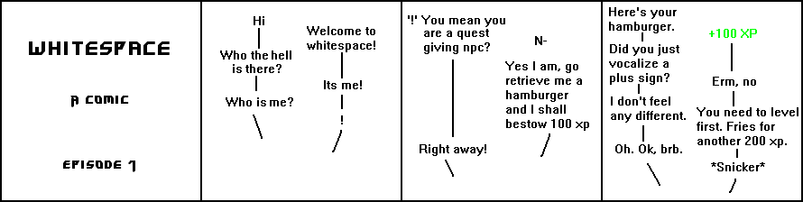
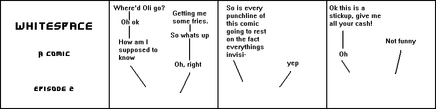

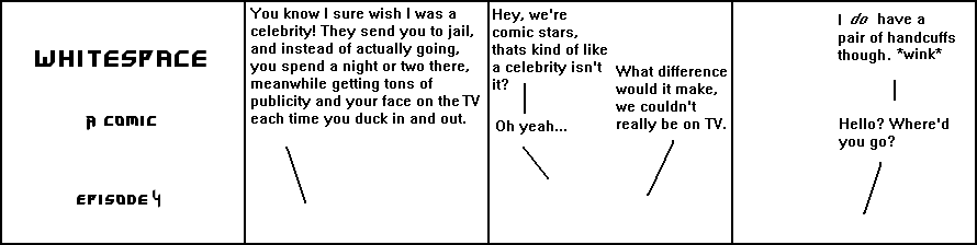

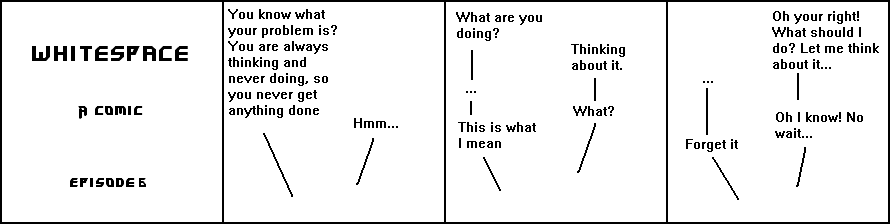
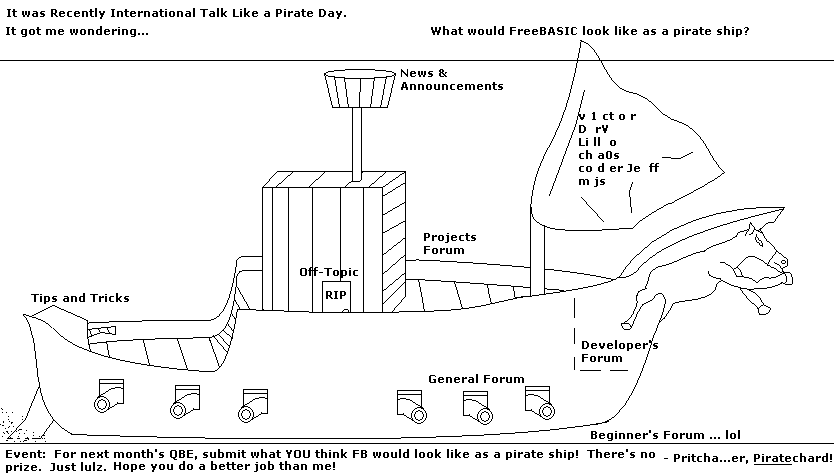
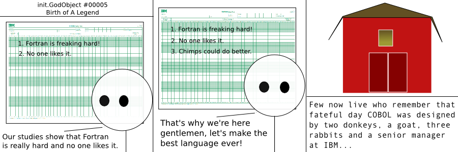

