Add LED tool work lights and automatic charge monitors
Posted: Sat Apr 13, 2013 12:33 pm
Many people who enjoy programming also enjoy working on electronics.
I started to add LED work lights to some of my battery operated tools,
but I found that LED lights are not really friendly with 110 volts.
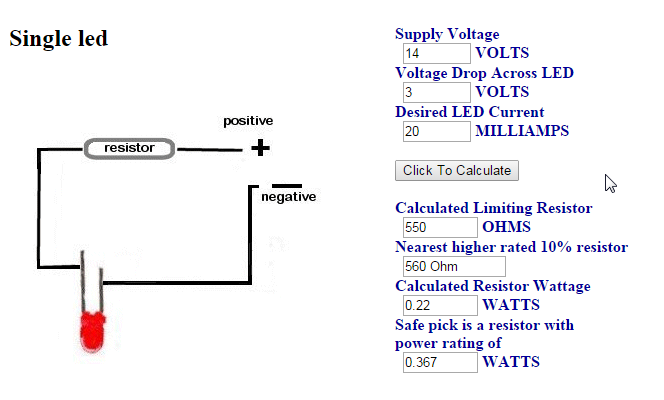
LEDs only need about 3 volts and around 20 milliamps of current.
Normally you would need a large resistor to reduce 110 volts down to 3 volts.
The reduction of 107 volts would also require a power resistor and a lot
of heat or a complicated power supply that might not fit into a tool easily.
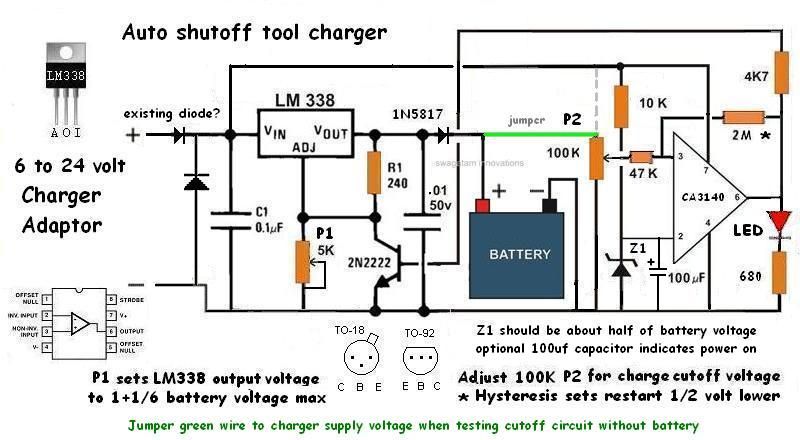
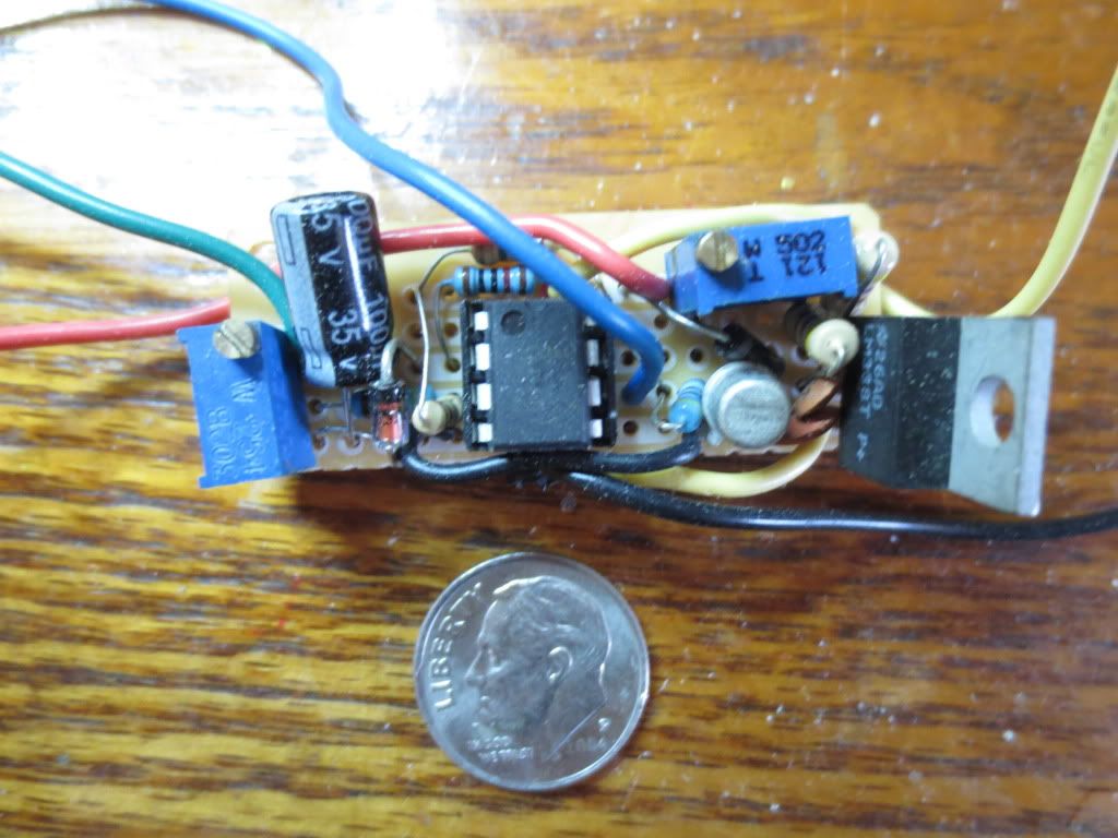
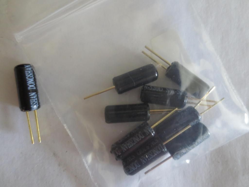
The following circuit just uses a .47 uf capacitor rated at 200 volts or more
and a 1000 ohm 1/2 watt resistor to power up to two super bright LEDs:
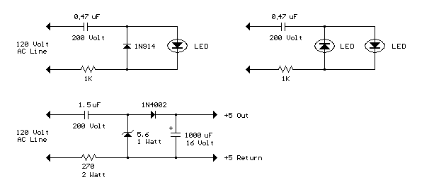
The circuit LEDs and diodes create about 1.7 volts DC with AC peaks supplying an average of 3 volts.
Each LED would use about 10 ma current on average. About half of a DC circuit.
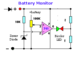
The lower circuit is an example of obtaining a low regulated voltage from the AC line. The zener diode serves as a
regulator and also provides a path for the negative half cycle current when it conducts in the forward direction.
In this example the output voltage is about 5 volts and will provide over 30 milliamps with about 300 millivolts
of ripple. Use caution when operating any circuits connected directly to the AC line.
http://www.bowdenshobbycircuits.info/pa ... ineled.gif
Note: Always be careful when working with household voltages as they can kill you!
Never touch wiring with the unit open and plugged in! You may have voltages where not expected!
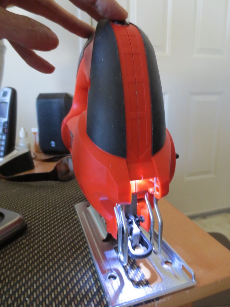
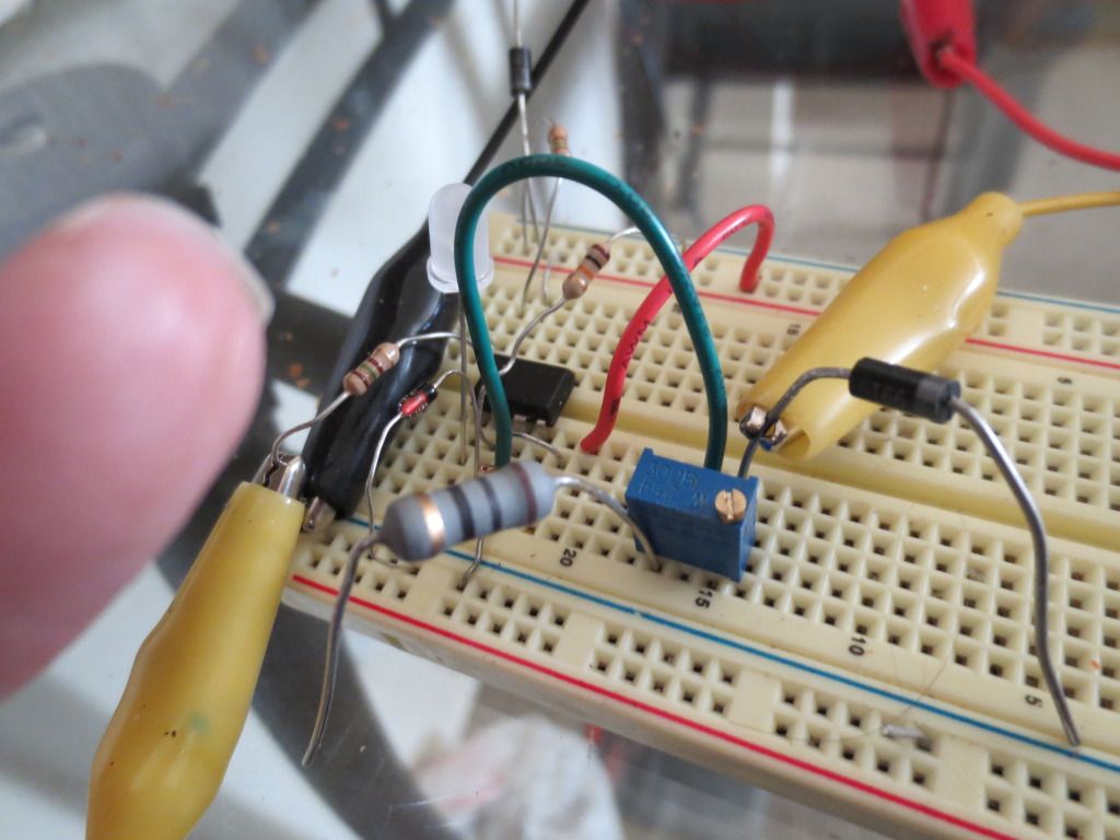
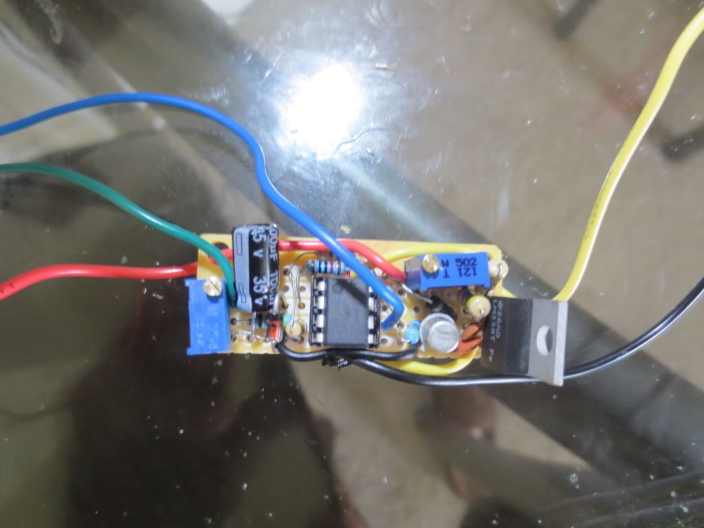
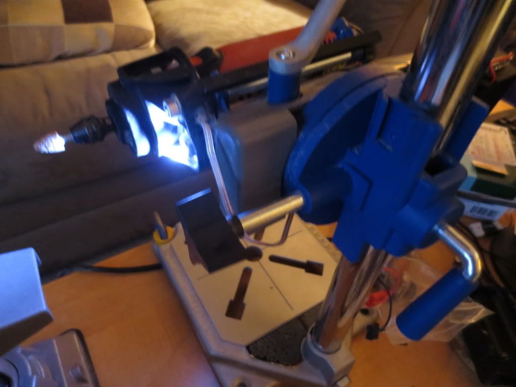
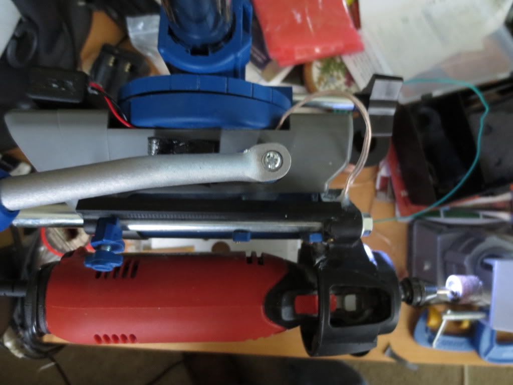
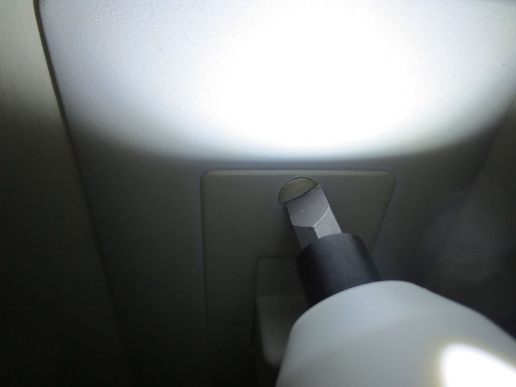
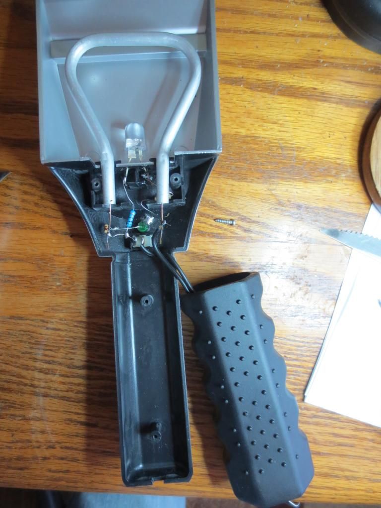
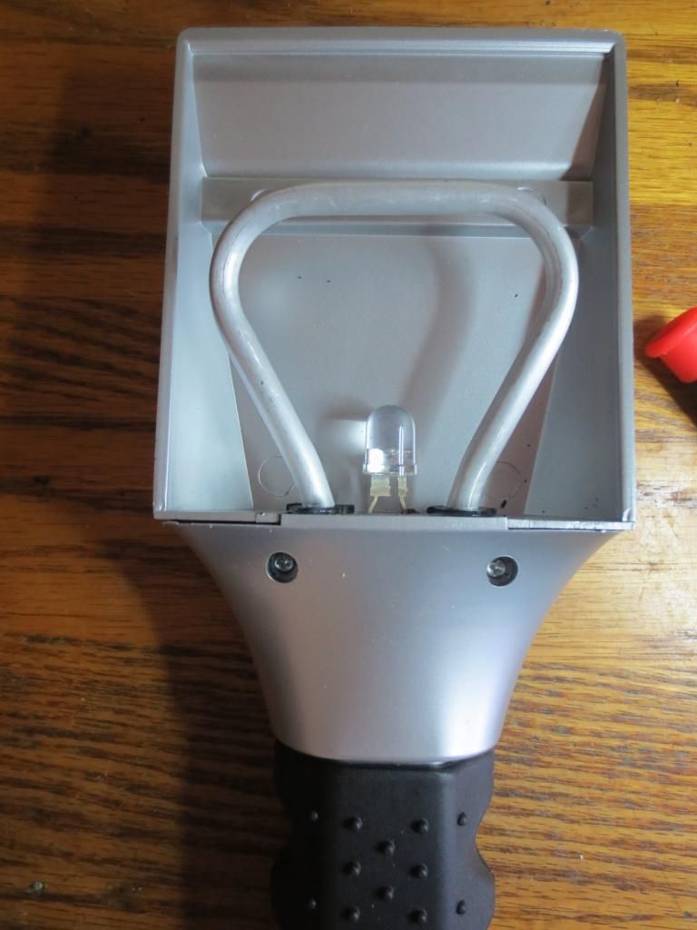
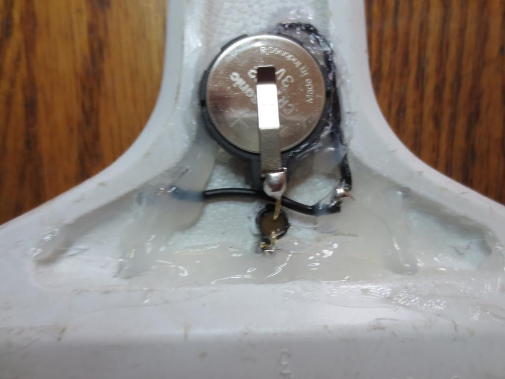
The Black and Decker jigsaw below has a lot of room for a pushbutton switch and the simple power supply components.
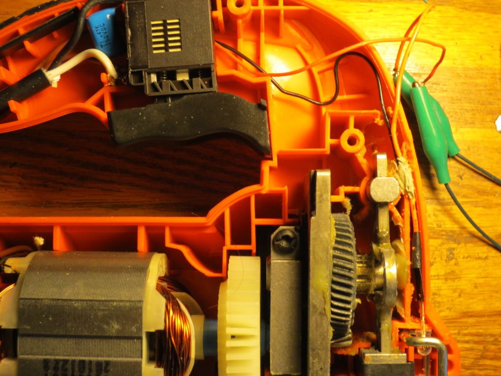
Locating the LED light was another matter. Not much room near the front by the blade and metal guard!
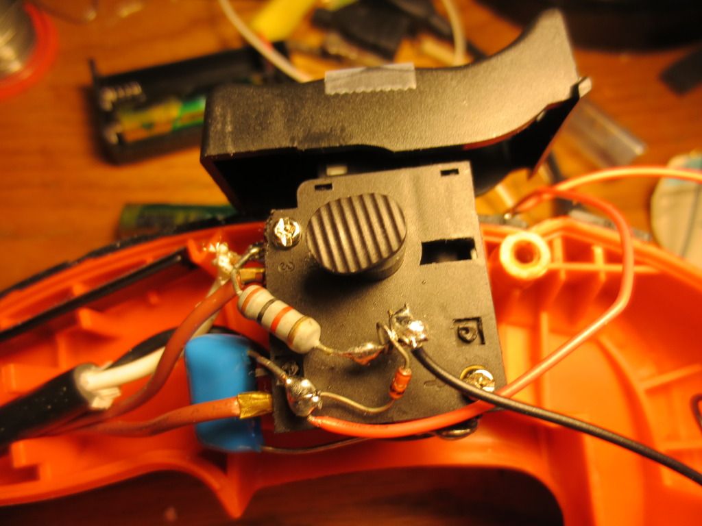
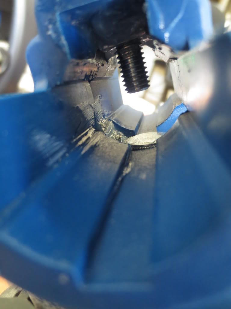
I chose to mount the power supply behind the trigger switch to keep the 110 volts in a safe place.
And yes, the 110 volt terminals on the trigger switch are not insulated! Be careful!
The 1N914 diode is required when using just one LED to bypass reverse voltages.
Since the trigger has a variable speed, I just used the 110 volts that came into the trigger
rather than supplying variable speed voltages.
The black wire is hot wire and white is the return line directly from the power cord.
The heavy red wires are 110 volts to motor. They carry high voltages too!
The red and black wires to the right of trigger are the LED wires.
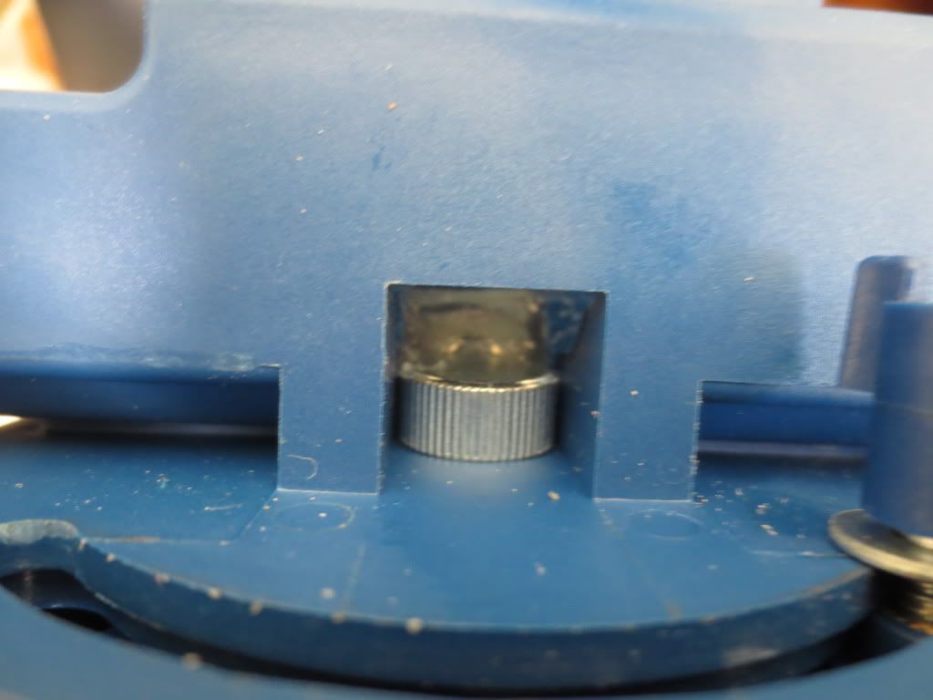
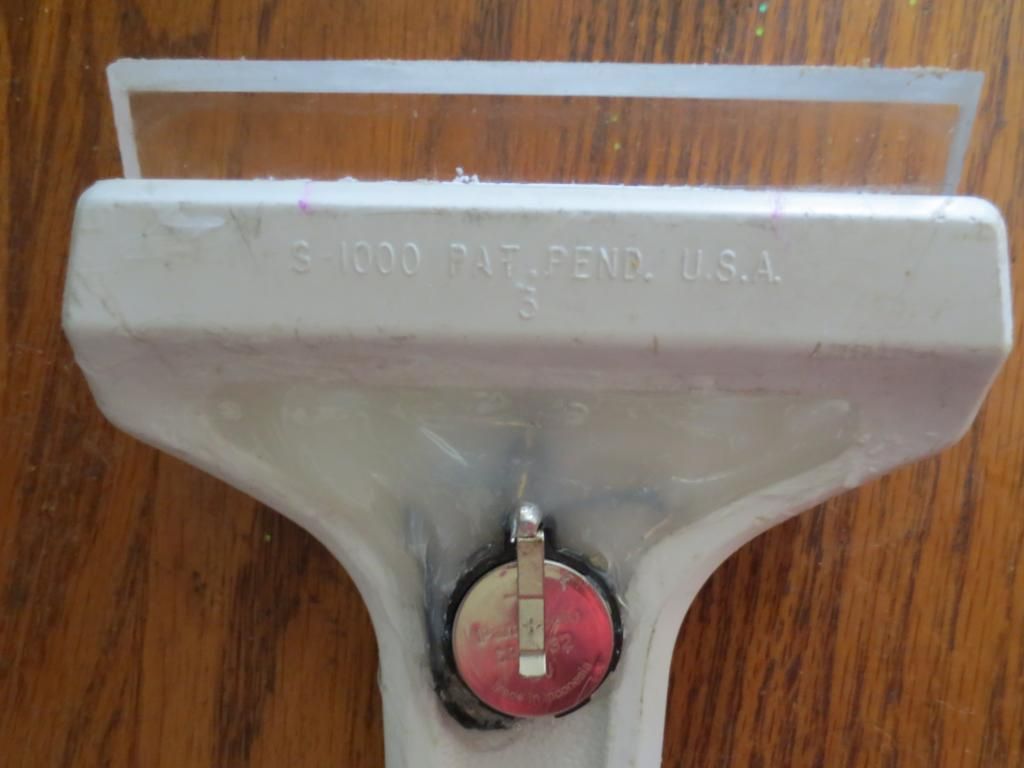
A momentary pushbutton switch can be placed on top, ahead of the trigger
so that a user can press it easily with their thumb when needed:
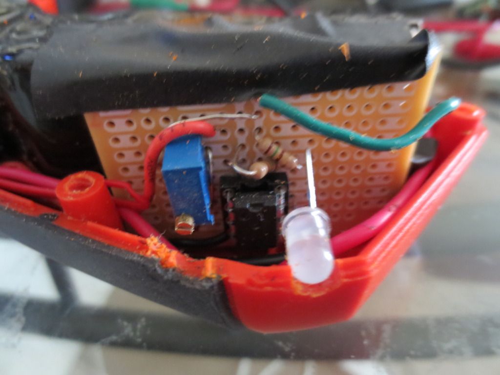
All open circuit wiring was tape insulated to prevent electrocution later.
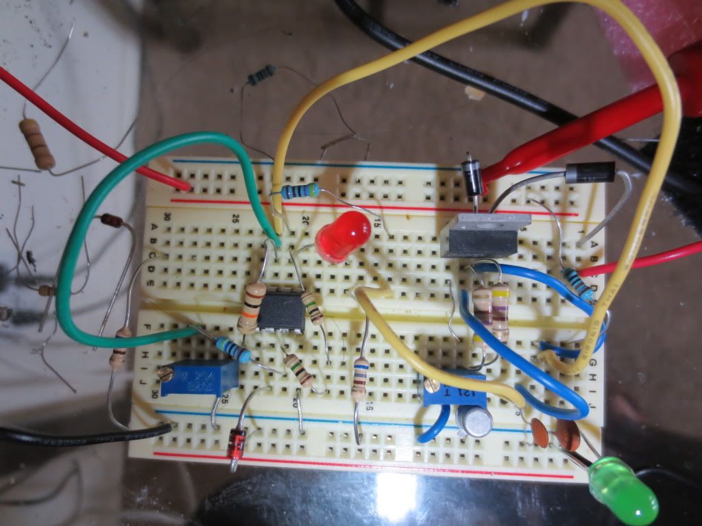
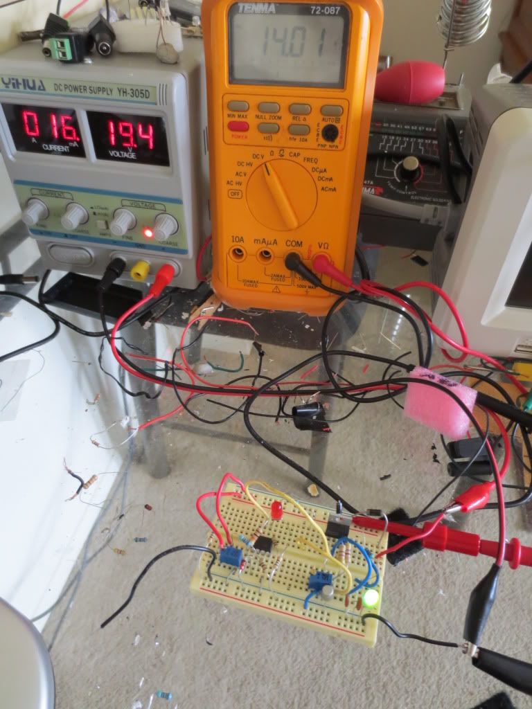
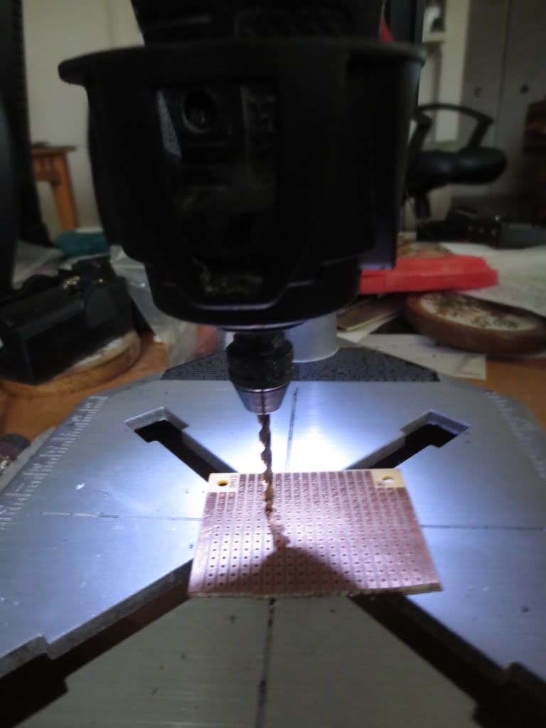
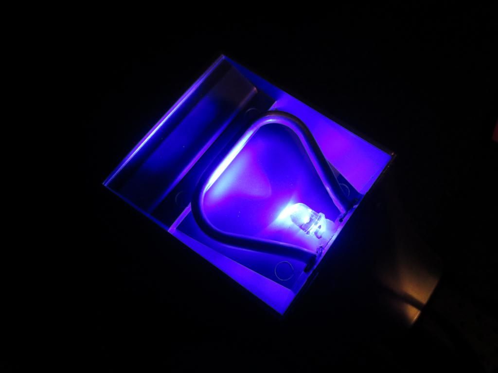
Here is the final test of the circuit before I added a momentary pushbutton switch:
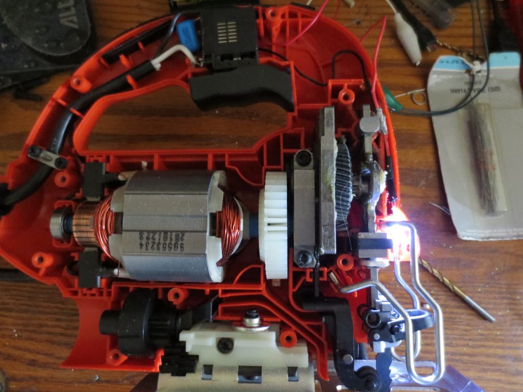
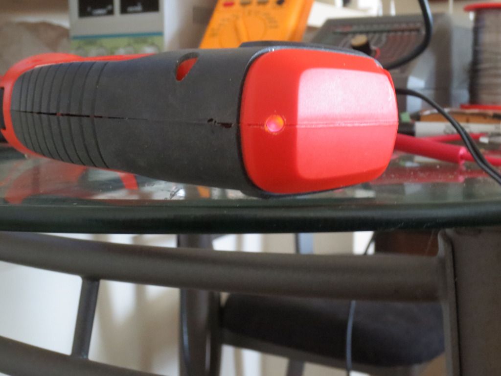
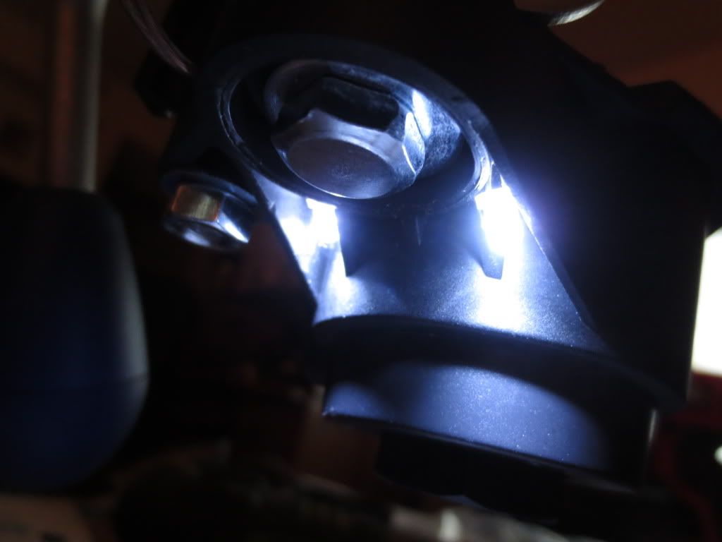
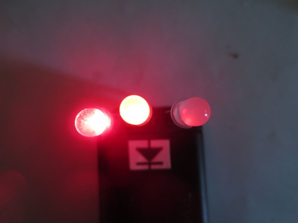
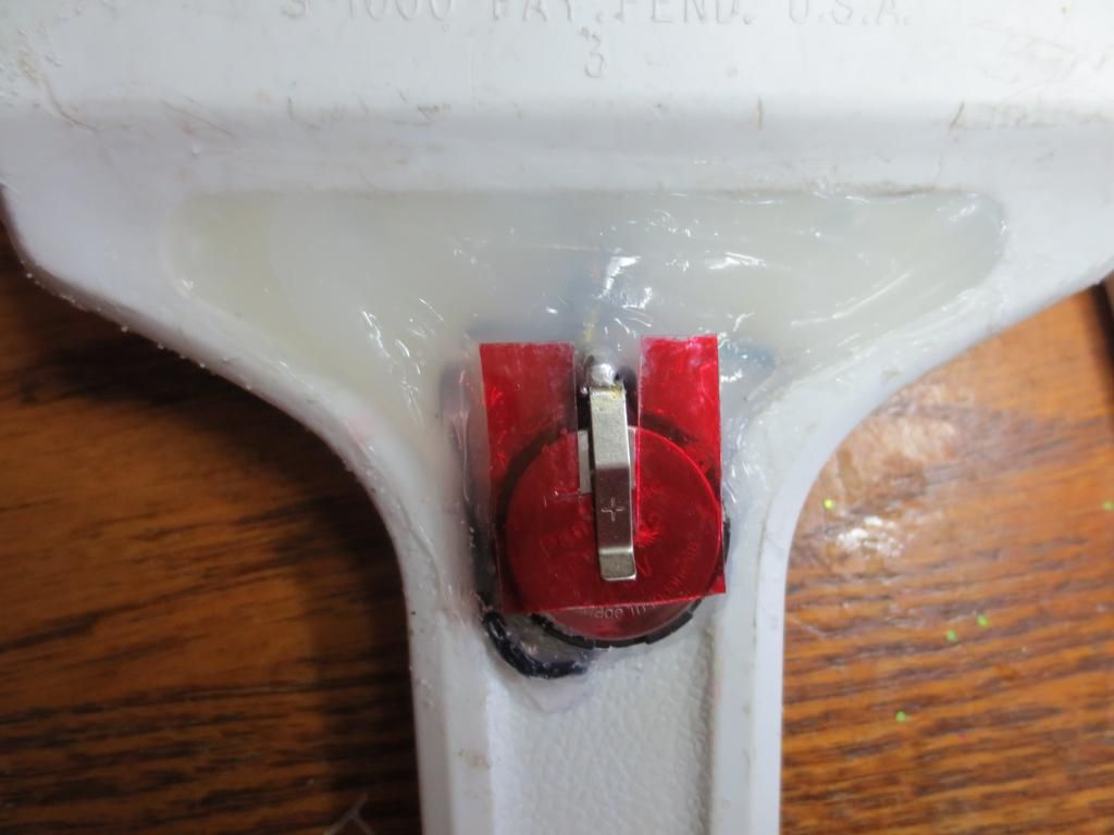
The LED lights up the front of the blade work area. I later decided to add another LED
behind the blade by eliminating the diode from the trigger switch circuit
and wiring the second LED in it's place after the pushbutton switch.
The two LEDs should be wired in opposing directions so that both halves of the AC voltage is used.
Normally the long LED leg is the anode or positive lead in DC circuits.
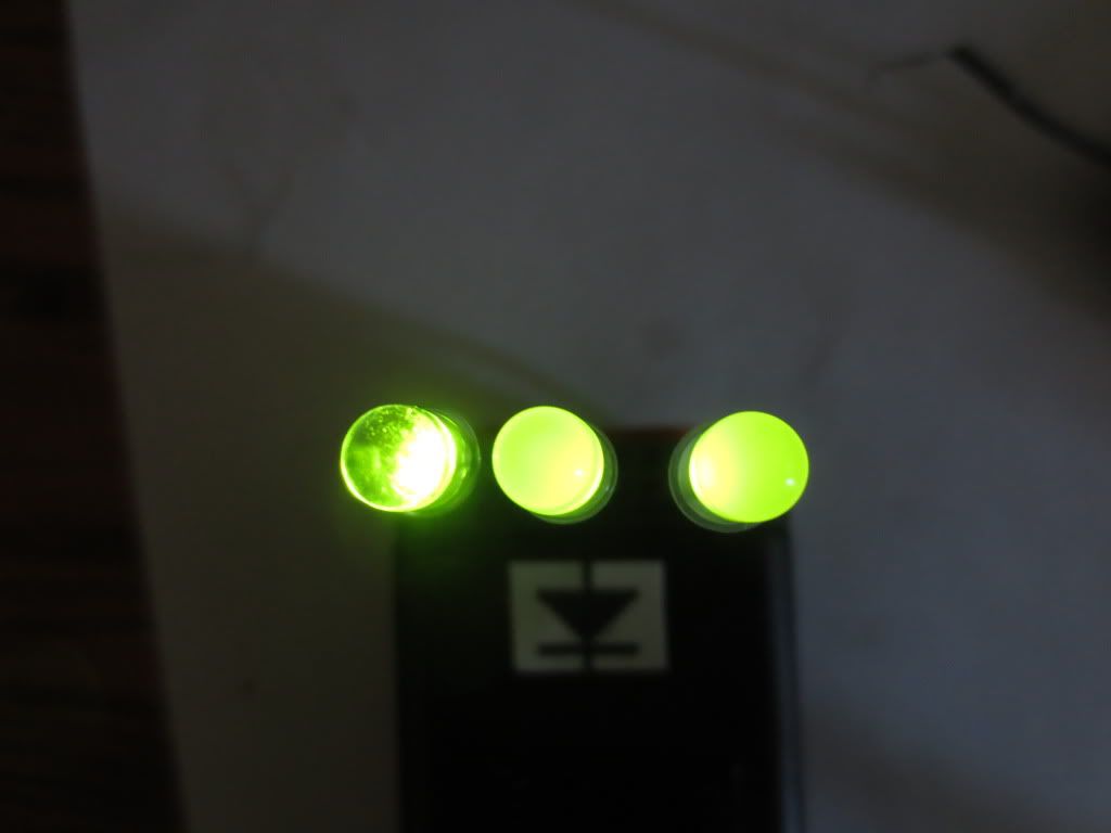
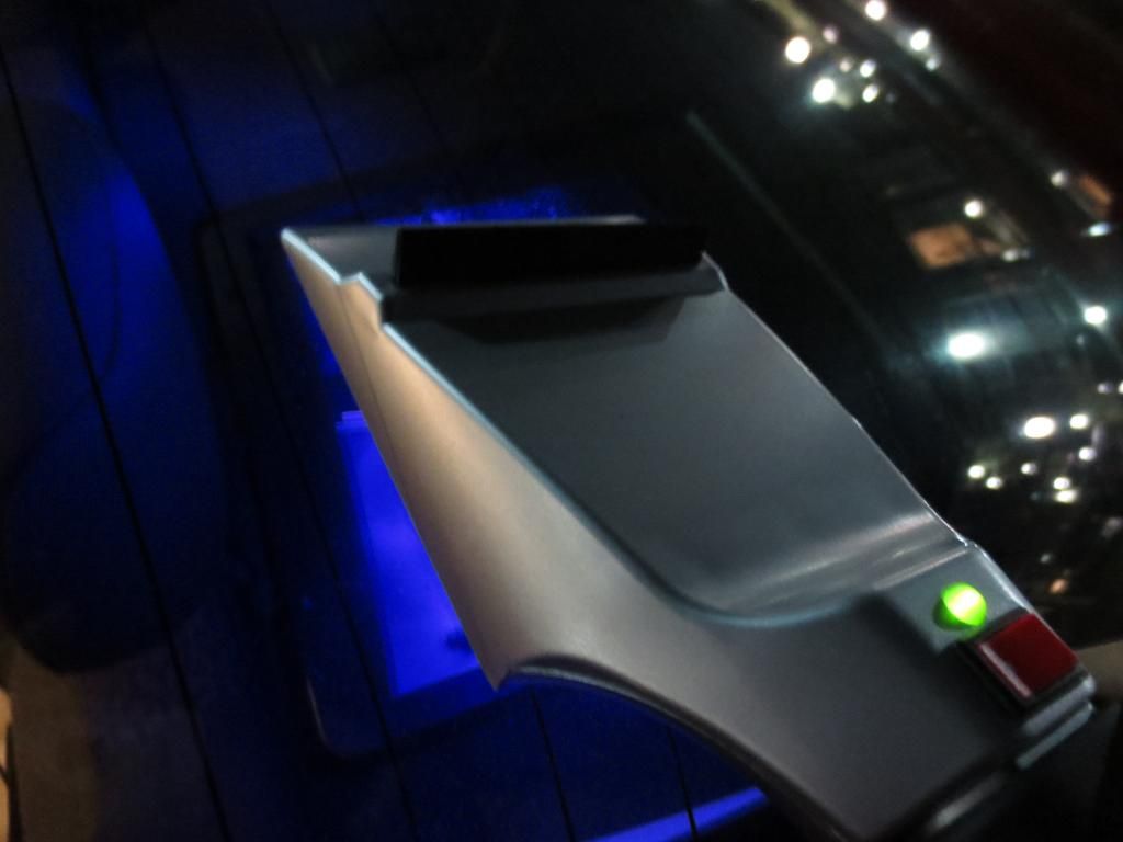
Final product:
QB Capacitive reactance formula determines currents supplied by high voltage AC capacitors:
Reference: http://www.allaboutcircuits.com/vol_2/chpt_4/2.html
I started to add LED work lights to some of my battery operated tools,
but I found that LED lights are not really friendly with 110 volts.
LEDs only need about 3 volts and around 20 milliamps of current.
Normally you would need a large resistor to reduce 110 volts down to 3 volts.
The reduction of 107 volts would also require a power resistor and a lot
of heat or a complicated power supply that might not fit into a tool easily.
The following circuit just uses a .47 uf capacitor rated at 200 volts or more
and a 1000 ohm 1/2 watt resistor to power up to two super bright LEDs:
The circuit LEDs and diodes create about 1.7 volts DC with AC peaks supplying an average of 3 volts.
Each LED would use about 10 ma current on average. About half of a DC circuit.
The lower circuit is an example of obtaining a low regulated voltage from the AC line. The zener diode serves as a
regulator and also provides a path for the negative half cycle current when it conducts in the forward direction.
In this example the output voltage is about 5 volts and will provide over 30 milliamps with about 300 millivolts
of ripple. Use caution when operating any circuits connected directly to the AC line.
http://www.bowdenshobbycircuits.info/pa ... ineled.gif
Note: Always be careful when working with household voltages as they can kill you!
Never touch wiring with the unit open and plugged in! You may have voltages where not expected!
The Black and Decker jigsaw below has a lot of room for a pushbutton switch and the simple power supply components.
Locating the LED light was another matter. Not much room near the front by the blade and metal guard!
I chose to mount the power supply behind the trigger switch to keep the 110 volts in a safe place.
And yes, the 110 volt terminals on the trigger switch are not insulated! Be careful!
The 1N914 diode is required when using just one LED to bypass reverse voltages.
Since the trigger has a variable speed, I just used the 110 volts that came into the trigger
rather than supplying variable speed voltages.
The black wire is hot wire and white is the return line directly from the power cord.
The heavy red wires are 110 volts to motor. They carry high voltages too!
The red and black wires to the right of trigger are the LED wires.
A momentary pushbutton switch can be placed on top, ahead of the trigger
so that a user can press it easily with their thumb when needed:
All open circuit wiring was tape insulated to prevent electrocution later.
Here is the final test of the circuit before I added a momentary pushbutton switch:
The LED lights up the front of the blade work area. I later decided to add another LED
behind the blade by eliminating the diode from the trigger switch circuit
and wiring the second LED in it's place after the pushbutton switch.
The two LEDs should be wired in opposing directions so that both halves of the AC voltage is used.
Normally the long LED leg is the anode or positive lead in DC circuits.
Final product:
QB Capacitive reactance formula determines currents supplied by high voltage AC capacitors:
Code: Select all
'Inductive Reactance = 2*pi*frequency*inductance
'Capacitive Reactance = 1/(2*pi*frequency*capacitance)

DO
  INPUT "Enter AC supply voltage: ", voltage& '= 120
LOOP UNTIL voltage& > 0

ACfreq = 60 ' 50 'in Europe and Asia?
DO
  INPUT "Capacitor farads(1uf = .000001) or microfarads >= .001:"; capacity ' EX:.068 = .000000068
LOOP UNTIL capacity > 0

IF capacity >= .001 THEN capacity = capacity / 1000000

PRINT USING "Capacity = .############ farads"; capacity

Creact& = 1 / (8 * ATN(1) * ACfreq * capacity)

PRINT USING "Reactance = ########,.## ohms"; Creact&
PRINT
INPUT "Enter other series resistance or hit enter to continue: ", add
PRINT
RMScurrent = voltage& / (Creact& + add)
current = .9 * RMScurrent * .5 'cap current is 90 degrees off of voltage sync
PRINT USING "Average supply Current = ##.##### amps"; current


