Electronic projects using LEDs

Discuss whatever you want here--both QB and non-QB related. Anything from the DEF INT command to the meaning of life!

Moderators: Pete, Mods

User avatar
burger2227
Veteran
Posts: 2466
Joined: Mon Aug 21, 2006 12:40 am
Location: Pittsburgh, PA

Post by burger2227 »

Not everything you find on the internet works like it says:

Image

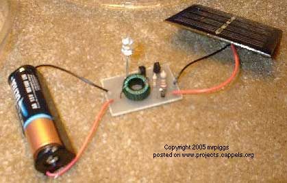
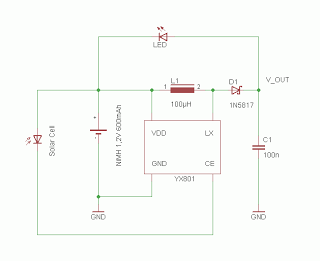
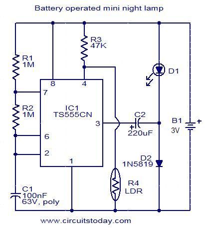
I just got the parts necessary to try the circuit above, but it does not work as described. I should have noticed
a big flaw right from the start, the light never shuts off! It can't because the current flows automatically through
the LED and diode without the other circuitry. Another article says the low power 7555 timer is supposed to
double the voltage so that it can be run off of one 1.5 volt battery, but it needs two to light at all! When it
gets dark it just causes the LED to blink at best! At worst, nobody ever tested the circuit to begin with.

Remove the 220 capacitor and the diode and move the LED down to where the diode was and you get a strobe
effect when the LDR or photocell gets darker.
Image
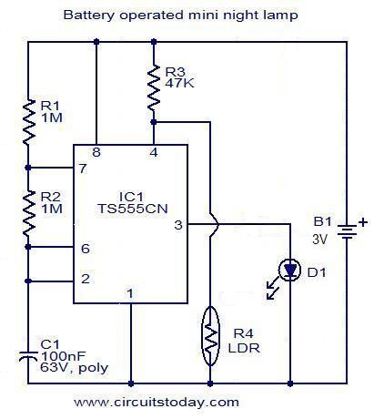
Remove the other capacitor and the light comes on when the LDR gets dark. Adjust the 47K resistance for sensitivity.
I don't have a scope to see what the timer is doing, but it turns the LED on immediately when it gets darker. The current
draw on the batteries is 100 uA off and 200 uA on. That compares with 25 uA off and 130 uA on with the circuit below.

Image

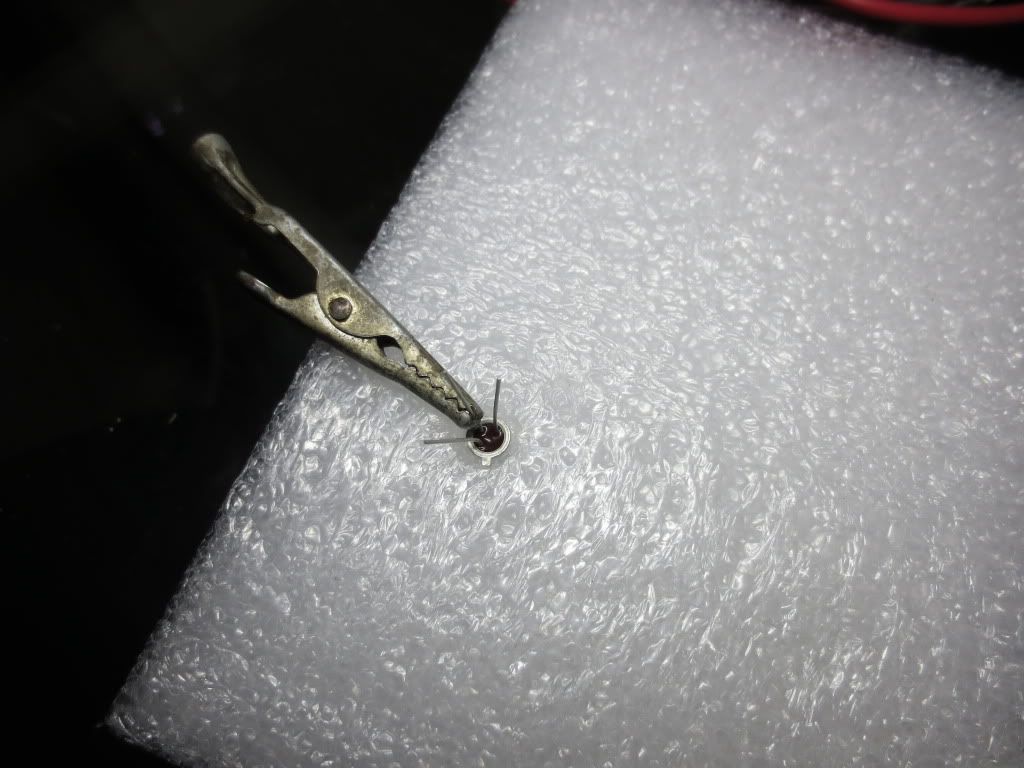
Photocells come in different low resistance ranges with most going up to 1 megaohms when dark so the
40,000 ohm resistance can be adjusted for greater of less sensitivity. This circuit comes on slowly as it
gets darker saving more battery life. The 555 LED seems slightly brighter because it generates a square wave.

Image

Found another promising circuit I may be able to adapt:

Image
(C) Courtesy of Tony Van Roon

The voltage requirements are higher and it will draw more battery current than a super bright LED
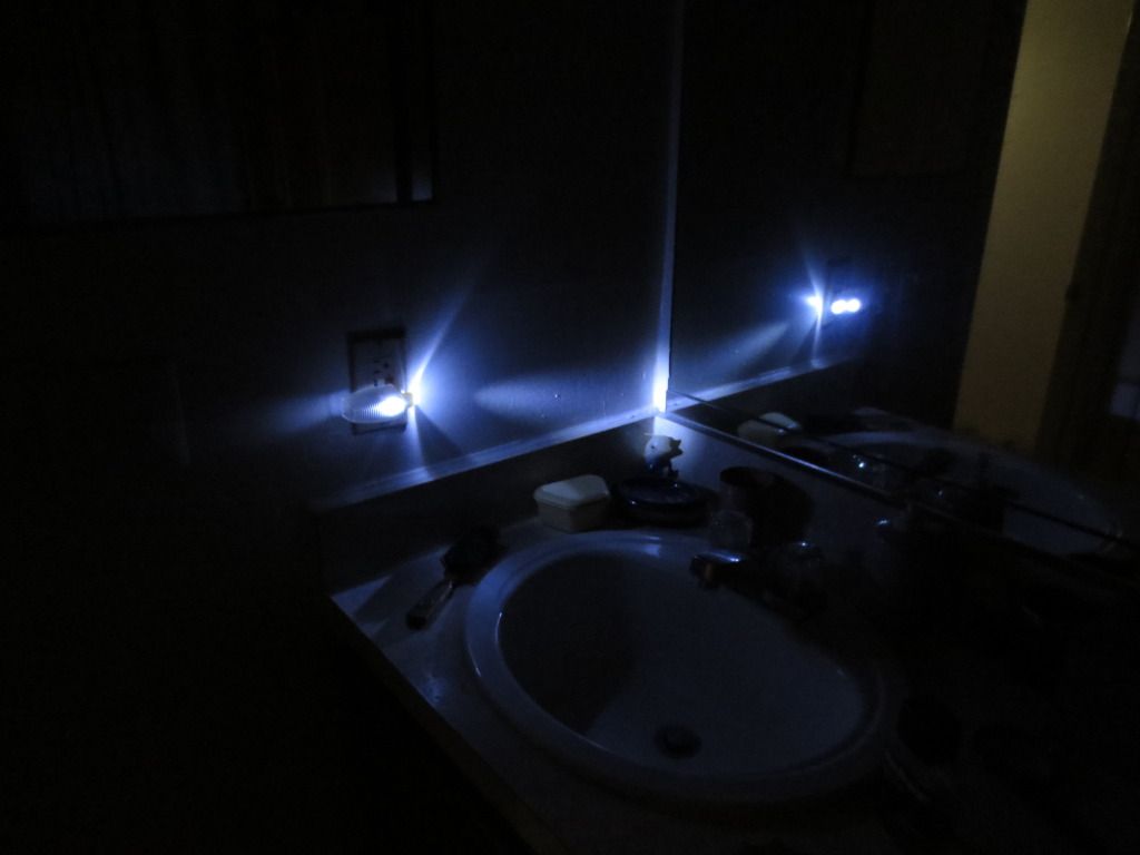
would alone. So far the simple circuit has been running for 2 days on 3 volts with little brightness change.
Last edited by burger2227 on Thu Mar 21, 2013 7:08 am, edited 1 time in total.
Please acknowledge and thank members who answer your questions!
QB64 is a FREE QBasic compiler for WIN, MAC(OSX) and LINUX : https://www.qb64.org/forum/index.php
Get my Q-Basics demonstrator: https://www.dropbox.com/s/fdmgp91d6h8ps ... s.zip?dl=0
iamdenteddisk
Veteran
Posts: 185
Joined: Mon Jun 30, 2008 4:10 pm

Post by iamdenteddisk »

really nice stuff, did you know that you can use those LDR circuits to automate processes?

use a black plastic tube (heat shrink) and mate the business end of both an led and a LDR inside the tube facing each other then heat the end of the tube to shut out any light.

this is called "optical isolation" and is very useful if you want to say turn on a night light or saw using a micro controller or PC..

the best part is the ease of merging two separate circuit voltages without any worry of shorting exploding battery or getting burned.

best is to practice switching a night light from a basic stamp or arduino driving the LED first. once you get the jist of how it works you can move on to switching higher currents.
User avatar
burger2227
Veteran
Posts: 2466
Joined: Mon Aug 21, 2006 12:40 am
Location: Pittsburgh, PA

Post by burger2227 »

Yeah they have Optoisolator chips to do that too. Use them for output from the LPT data port with
a separate power supply.

The simple LED transistor circuit has been turning on and off all week. It draws 3 ma with brand
new batteries so it should last about 40 days. The LED is bright enough to see on the ceiling like a
3 volt flashlight.
Please acknowledge and thank members who answer your questions!
QB64 is a FREE QBasic compiler for WIN, MAC(OSX) and LINUX : https://www.qb64.org/forum/index.php
Get my Q-Basics demonstrator: https://www.dropbox.com/s/fdmgp91d6h8ps ... s.zip?dl=0
iamdenteddisk
Veteran
Posts: 185
Joined: Mon Jun 30, 2008 4:10 pm

Post by iamdenteddisk »

Are you etching boards for these circuits or are they breadboard experiments only?

I sometimes use pieces of sturdy plastic like CD cases for doing wire wrap type circuits. by drawing my schematic directly on the plastic with a sharpie then drill the holes for components and wire wrap and solder them at the underside. typically I make a bump on the components legs that holds the component a bit off the board then brad the legs open underneath to lock it in place. for circuit traces between components I use magnet wire that is rated for the current being used, it's enamel coating insulates well. it works as well as perf board but has a more science project finished look. if it is to be shown a thick spray coating of clear enamel works as well as a enclosure box to prevent shock or shorting.

though I do etch real boards for things that are "not just novelty experiments", the DIY stuff above can cut cost for prototyping. Glad to see you really getting into EET Ted, from the looks of it your getting a good workbench and tool-set together. hope you find it as self rewarding as I have, from the looks of that work light on the jigsaw, you are!
User avatar
burger2227
Veteran
Posts: 2466
Joined: Mon Aug 21, 2006 12:40 am
Location: Pittsburgh, PA

Post by burger2227 »

I haven't etched boards for a long time now. I'm just getting back to an old hobby. I sold all of
my old electronics stuff last year, so I have to start all over. My eyes are not as good now either.
I use Radio Shack pre-drilled copper clad boards and jumpers. Nothing fancy.

I'll be wiring my own coils pretty soon so that I can get LED's to light with one battery.

Image

I'm waiting on the ferrite coils. Etching is messy and I don't have a garage anymore...

Image

I'll post my results and photos when I get all of the parts. They take a while coming from China.
Last edited by burger2227 on Thu Mar 21, 2013 8:31 pm, edited 1 time in total.
Please acknowledge and thank members who answer your questions!
QB64 is a FREE QBasic compiler for WIN, MAC(OSX) and LINUX : https://www.qb64.org/forum/index.php
Get my Q-Basics demonstrator: https://www.dropbox.com/s/fdmgp91d6h8ps ... s.zip?dl=0
iamdenteddisk
Veteran
Posts: 185
Joined: Mon Jun 30, 2008 4:10 pm

Post by iamdenteddisk »

totally love it, a solar based joule thief..pretty awesome sir..

I am now working on a duplicating a bidini SSG battery charger to add as an addition to my solar home project. perhaps I can get some photos taken to share the project here also..

I just got a simulate-able schematic in LTSpice of it working, I want to fully explain it using physics and not the BS Ethers mumbo jumbo.

I can already explain how it works but this gives real physical proofs with duplicate-able numbers. something I don't think anyone has yet done. as all that I can find online is the witch doctor's rant of dark matter when it is simply a magneto charging device driven by a clock pulse motor.

just like a lawn tractor or motor cycle maintains it's battery's using a magneto or stator only this is driven by a up-scaled version of the quarts watch.. will share soon.

try doing the simulation and use an amp-meter on the battery, it say's it's charging the battery that is driving the circuit.

http://dl.dropbox.com/u/24429764/my_bediniSSG.asc
User avatar
burger2227
Veteran
Posts: 2466
Joined: Mon Aug 21, 2006 12:40 am
Location: Pittsburgh, PA

Post by burger2227 »

Yes the coil doubles the voltage to light most 3 volt bright LED's. I've never tried working with coils
before. I also have 2 garden solar lights to play with. They use 100 mh coils and a special 4 legged
chip to control the LED's. The two transistors do the same thing in the circuit above.

I also have a 4.5 volt solar panel that I got from Radio Shack that creates about 1.5 volts in normal
room light. Perhaps it can help charge a battery and contol it. The simple transistor circuit is drawing
less than 3 ma when it is on, but it is still pretty bright. I adjusted the 40K resistor value up with a
trimmer so that room lights turn it off too.

PS: The biggest problem here is posting! I keep getting invalid posts that take off my signature
at times. Do you?
Please acknowledge and thank members who answer your questions!
QB64 is a FREE QBasic compiler for WIN, MAC(OSX) and LINUX : https://www.qb64.org/forum/index.php
Get my Q-Basics demonstrator: https://www.dropbox.com/s/fdmgp91d6h8ps ... s.zip?dl=0
iamdenteddisk
Veteran
Posts: 185
Joined: Mon Jun 30, 2008 4:10 pm

Post by iamdenteddisk »

so far I haven't had an issue with losing signatures but I do have to log in before, during and after posting. it keeps giving errors and saying invalid session. it is inconvenient to say little but being on wifi, it may be because of unsecured connection IDK? I can deal with it though as it is a trade off situation I am almost used to..

aren't you admin of this board Ted?

I know on my forum there is tons of switches and things that get easily confused or toggled by accident in the admin interface, I eventually just narrowed down to a single forum to get working the way I wanted and each additional forum after are just copied,re-named, permissions and all..
User avatar
burger2227
Veteran
Posts: 2466
Joined: Mon Aug 21, 2006 12:40 am
Location: Pittsburgh, PA

Post by burger2227 »

LED is the next generation's light! Here is some code that calculates the resistor values:

Code: Select all

PRINT "Note that car LED voltages may be as high as 14 volts due to charging!"
PRINT
DO
  INPUT "Enter DC power supply or battery voltage to be used >= 1.5: ", volts
LOOP UNTIL volts >= 1.5
DO
  INPUT "Enter the DC voltage required by the LED to light <= supply voltage: ", LEDV
LOOP UNTIL LEDV > 0 AND LEDV <= volts

IF LEDV = volts THEN
  PRINT "No current limiting resistor is required!"
ELSE: Vdrop = volts - LEDV
  PRINT "A resistor is required to drop "; Vdrop; "volts"
  DO
    INPUT "Enter LED current required to light the LED properly in milliamps: ", MA
  LOOP UNTIL MA > 1 AND MA < 500

  MA = MA / 1000
  resistor& = Vdrop / MA
  watts = (MA ^ 2) * resistor& * 1.5
  PRINT "Resistor required is"; resistor&; "ohms at"; watts; "watts."
END IF
Note: I had to check the Disable HTML checkbox to get > and < to work properly in this post:

V = IR works by determining the voltage drop necessary to run the LED with the rated voltage.
Running an LED at a higher than rated voltage might make it brighter or burn it out faster!

Most LED packages will tell you the milliamps of current required. To test for current and voltage
requirements use a variable power supply or batteries starting at 1 battery and increase the voltage
up to 3 volts for most LED's. Normally an LED will draw between 10 and 20 milliamps of current maximum.


Here is a site that can help with more LED's in series or parallel:

http://led.linear1.org/led.wiz" target="_blank

Use a resistor value and wattage that is higher than the value returned for the longevity of the LED and resistor!
Please acknowledge and thank members who answer your questions!
QB64 is a FREE QBasic compiler for WIN, MAC(OSX) and LINUX : https://www.qb64.org/forum/index.php
Get my Q-Basics demonstrator: https://www.dropbox.com/s/fdmgp91d6h8ps ... s.zip?dl=0
User avatar
burger2227
Veteran
Posts: 2466
Joined: Mon Aug 21, 2006 12:40 am
Location: Pittsburgh, PA

Post by burger2227 »

Here is an interesting LED power failure light circuit. It combines the 120 volt capacitor idea with the
LED coil circuit.

Image
Power failure light project

The article says that the LED only stays on for a few minutes so I think the coils take a lot of
battery power. Perhaps I can incorporate the simple transistor LDR circuit instead. After all,
who needs an emergency power light in the day time?

Since the .068 uf high voltage capacitor is a lot smaller than the .47 uf ones I used for the tools,
I doubt it generates 3 volts of voltage so no wonder it did not last long with two batteries in series
in his prototype.

I made a night lite with 2 10mm LED's that has been running all day to light my dark bathroom.
The second LED comes out of the switch hole on top which I drilled out.
Image
The night light uses the exact circuit shown in the first post of this thread. It has no fuse, discharge resistor or varistor
Image

The light reflecting in the mirror helps too. It gives enough light to do your thing! With 2 LED's you
don't have much room for safety considerations. I won't leave it plugged in when I am away for
long periods just in case. It is plugged into a Ground Fault Protected outlet.

Always use Mica capacitors rated at 200 volts or more! Paper ones do not last and can
accumulate moisture or catch fire! I found out that the capacitor does not retain much voltage
after it is unplugged. Touching both plug leads does light up the LED's a bit however... perhaps
a 1 meg resistor across the capacitor is a good idea to be safe.


I finally got the ferrite cores. They are less than the size of a dime for a buck each.
Image

To make this circuit I will need to find a suitable enclosure with a 120 volt plug for the wall.
Any ideas where I can buy a 110 volt enclosure for it cheap?
Last edited by burger2227 on Mon Jun 17, 2013 1:56 pm, edited 5 times in total.
Please acknowledge and thank members who answer your questions!
QB64 is a FREE QBasic compiler for WIN, MAC(OSX) and LINUX : https://www.qb64.org/forum/index.php
Get my Q-Basics demonstrator: https://www.dropbox.com/s/fdmgp91d6h8ps ... s.zip?dl=0
iamdenteddisk
Veteran
Posts: 185
Joined: Mon Jun 30, 2008 4:10 pm

Post by iamdenteddisk »

we all have these utility or tool boxes taking up space in closets where we just take the tools out for use and they end up living in our main tool box.
Image
they are usually hollow injection molded plastics
having the tool shapes cast in to hold things x-mas present perfect. "I hate trying to pry tools out of"
Image
so I use these boxes for project enclosures by cutting the tool holding layer away with a box cutter or hot iron like a soldering iron or wood burner. its much safer to use the iron than a knife as a slip could sever an artery or lop off your baby maker but that choice and outcome is up to you.
Image
once you get these layers cut away you are left with a hollow cavity to place your project and now you can drill wholes for pot knobs or switches.
Image
in this project box there was a flap that had a second side to the box the little flap covered more tools but I had space in that area to place my project and the flap made a cool console panel for the project
the last picture is a mock up of my control panel for the project.
Image

tic-tac boxes or near anything that can hold your project in isolation will work the only things to consider is any heat made by the project melting the box or Faraday shielding to block stray signal in or out interfering.

a Faraday shield can be made by lining the box with tin foil, venting wholes or fans can be used to keep things cool but make sure if you shield it to also make sure the shielding cant short the pins of your project by adding a insulator of some sort even a gob of hot glue layered up will work there.
User avatar
burger2227
Veteran
Posts: 2466
Joined: Mon Aug 21, 2006 12:40 am
Location: Pittsburgh, PA

Post by burger2227 »

Problem is that I'd like to plug the failure light directly into the wall socket. I need a male plug
in the box. Maybe I can use a multiple outlet box if it is big enough and I can get it apart.
I could take a receptacle out and use the 3 holes for the 3 lites.

I contacted Dick Cappel and he has helped me figure out what is going on.

Here is a program I am working on:

Code: Select all

'Inductive Reactance = 2*pi*frequency*inductance
'Capacitive Reactance = 1/(2*pi*frequency*capacitance)

DO
  INPUT "Enter AC supply voltage: ", voltage& '= 120
LOOP UNTIL voltage& > 0

ACfreq = 60 ' 50 'in Europe and Asia?
DO
  INPUT "Capacitor farads(1uf = .000001) or microfarads >= .001:"; capacity '= .000000068
LOOP UNTIL capacity > 0

IF capacity >= .001 THEN capacity = capacity / 1000000: PRINT USING ".############ farads"; capacity

Creact& = 1 / (8 * ATN(1) * ACfreq * capacity)

PRINT USING "Reactance = ########,.## ohms"; Creact&

current = voltage& / Creact&

PRINT USING "Supply Current = ##.###### amps"; current

Wonder what electricity has to do with circles?... :wink:
Last edited by burger2227 on Sat Jun 15, 2013 10:08 pm, edited 7 times in total.
Please acknowledge and thank members who answer your questions!
QB64 is a FREE QBasic compiler for WIN, MAC(OSX) and LINUX : https://www.qb64.org/forum/index.php
Get my Q-Basics demonstrator: https://www.dropbox.com/s/fdmgp91d6h8ps ... s.zip?dl=0
iamdenteddisk
Veteran
Posts: 185
Joined: Mon Jun 30, 2008 4:10 pm

Post by iamdenteddisk »

I would think a socket like that is on old computer power supplies.
a "recessed male" to which you could use a standard PC chord to connect to power.

unless you mean you want to be able to plug a standard extension chord into your project box to power outside devices. in which case I would suggest a standard outlet heck even a blue plastic wall box and cover plate could do that pretty good looking if you leave the knockouts on the back side in place.


Im not sure I understood your post there but I answered both ways so just pick the one that fits.lol..
User avatar
burger2227
Veteran
Posts: 2466
Joined: Mon Aug 21, 2006 12:40 am
Location: Pittsburgh, PA

Post by burger2227 »

A cord would have it laying on the floor. I want it on a wall producing some light so that i can see.
Might as well have a socket to plug something else into it too. Most likely it will block both wall
receptacles.

Here is another coil circuit from a solar garden light:
Image

I can get the 100uH coil, but the 4 legged chip seems to be hogged by Chinese bulk sales
merchants on line. I'm going to try to chain two and use the middle to make a center tap perhaps.
My garden lamps are still working pretty well. They stay on longer at night as the days get longer.

Here is one using transistors. I found 470uH too. Dime each,
Image

http://www.talkingelectronics.com/proje ... Light.html

This is what I came up with using a photocell(LDR) to turn it off during the day:
Image
Use a 33K resistor from the transistor base to ground instead of 100K.
Eliminate the base capacitor altogether or it may blink on and off.

This night light circuit uses about 1 milliamp when off and 12 ma when the LED turns fully on.
Last edited by burger2227 on Sun Jun 16, 2013 12:58 pm, edited 2 times in total.
Please acknowledge and thank members who answer your questions!
QB64 is a FREE QBasic compiler for WIN, MAC(OSX) and LINUX : https://www.qb64.org/forum/index.php
Get my Q-Basics demonstrator: https://www.dropbox.com/s/fdmgp91d6h8ps ... s.zip?dl=0
User avatar
burger2227
Veteran
Posts: 2466
Joined: Mon Aug 21, 2006 12:40 am
Location: Pittsburgh, PA

Post by burger2227 »

I found a six outlet box that should work. I found that it comes apart pretty easily because the display
one in Lowes was already falling apart. The first thing I did was pull on it and off the cover came!

Image

I actually had pieces of it falling on the floor. It took me a while to put it back together as the copper
pieces interlink from above and below like a jigsaw puzzle. Thankfully they use both wall outlets so the
top or bottom sections can be taken out completely if you need more project space.

Image

It took a screwdriver and a little prying to get the plastic back cover off after removing the mounting
screw with it's clear plastic retainer. The center screw is supposed to go into the wall plate to mount it
permanently. It could be used with a nut to retain the back plate later. You might not want to glue it
permanently. Cost $4.30 just like the ones at Radio Shack without predrilled holes and the 110 volt plug.

Unfortunately the back cover does not cover the entire back of the box, but the prongs help hold it on
pretty well without glue! The back plate area is 3" X 3" and the entire box is about 4-3/4" X 3".

This 3 outlet box cost almost as much as the big one. After the screws are removed, it snaps apart.
Image

There isn't a lot of space, but the center outlet can be used alone by cutting the copper buses.
Both outlets are UL approved, sturdy plastic and pretty much fire proof!

Found two more at Walmart. The one on left has a sickly orange LED light at night. It has a circuit board
to turn it off, but it takes a lot of light to do that. I like the display lense for the LED's though. It also has
special Y screws that I haven't figured how to get off yet. Like somebody would even TRY to open one... :wink:

Image
The one on the right is similar to the other 6 outlet box, but it has a luminescent strip that apparently
runs off of 110 volts. There are two tubes with wires with springs on them going to the strip in the middle
on the front. There is room for one rechargeable battery in that space if the posts are melted away a bit.
Then just wrap some wire around the posts and force it in. The back plate covers the entire thing and pries
off with a bit of effort. I had to go around it several times to get it off. When taking the plates off, push
the metal prongs down so the guts don't spill all over the place.
Last edited by burger2227 on Tue Jun 11, 2013 12:59 pm, edited 4 times in total.
Please acknowledge and thank members who answer your questions!
QB64 is a FREE QBasic compiler for WIN, MAC(OSX) and LINUX : https://www.qb64.org/forum/index.php
Get my Q-Basics demonstrator: https://www.dropbox.com/s/fdmgp91d6h8ps ... s.zip?dl=0
iamdenteddisk
Veteran
Posts: 185
Joined: Mon Jun 30, 2008 4:10 pm

Post by iamdenteddisk »

sorry I missed the question in you post above about, "what do circles have to do with electricity?"

you are dealing with reactance which is a type of resistance that happens 2pi out of phase.

the best analogy I could come up with to explain it is a gun shot. when you shoot a gun you get an explosion where pressure rises linearly pushing the bullet out of the gun. once it exits pressure falls and a vacuum pressure sucks air back into the gun.

in an inductor a applied voltage 0deg produces a magnetic field 90 deg then as polarity changes 180 deg that field collapses and a induced voltage 270deg of reversed polarity is emitted from the coil, "which resist incoming current 360 deg".

now the incoming current is polar opposite to the induced voltage so the greater voltage wins the game of war like in cards.

now you might ask why it is 2pi in the formula when pi represents a 360 degrees of a circle.

the answer is which voltage you are calculating.

remember you want to calculate the induced voltage to find the inductance of the inductor as you should know the applied voltage..

capacitors work the opposite of inductors they charge then retain the charge slowly discharging through a resistance that changes due to the frequency of the charge discharge cycle. this charge plays the game of war with the next incoming peak of the same polarity winner passes through its gate.

that is why the reciprocal (1/) is the only difference in their formulas.

keep documenting your project as you go and ask any question you might have. I mean I can't explain how monkey's learned English in evolution or anything like that but EET questions, I can do..lol

make sure to share your final schematic before building to, I can tell you if it is laid out right or not. it might save you a re-do or wasted components..
User avatar
burger2227
Veteran
Posts: 2466
Joined: Mon Aug 21, 2006 12:40 am
Location: Pittsburgh, PA

Post by burger2227 »

According to Dick Cappel, the LED circuit current is limited by that capacitive resistance so that the
battery gets a trickle charge of 6 milliamps with 240 volts so 120 volts will only produce about half.
I may have to doulble the capacity by using 2 .068 capacitors in parallel to get a better charge.

Image
The cycles per second are relevant too as the reactance formula suggests.

The LED part of the circuit only works because of the batteries. Originally he tried to use just one
battery, but older white LED's would not light up. Maybe my newer ones will.
Last edited by burger2227 on Thu Apr 04, 2013 8:13 pm, edited 1 time in total.
Please acknowledge and thank members who answer your questions!
QB64 is a FREE QBasic compiler for WIN, MAC(OSX) and LINUX : https://www.qb64.org/forum/index.php
Get my Q-Basics demonstrator: https://www.dropbox.com/s/fdmgp91d6h8ps ... s.zip?dl=0
iamdenteddisk
Veteran
Posts: 185
Joined: Mon Jun 30, 2008 4:10 pm

Post by iamdenteddisk »

for the clock I think if you recessed the led you would not only block glaring light on the glass but loose the light reflecting from the clock face also which is good. I would suggest a small piece of mirror glued to the glass with the shiny side facing the clock or maybe even in an downward angle "casting light" but still allowing the light that would be blocked by recessing the led.

try a piece of electrical tape/foil on the glass right where the led is and it should give you and idea of what it be like with a mirror.

if it where not for knowing the actual intent of efficiency, I would have suggested el-wire about the inside of the door frame to illuminate the entire clock face..
Last edited by iamdenteddisk on Thu Mar 28, 2013 5:13 am, edited 2 times in total.
User avatar
burger2227
Veteran
Posts: 2466
Joined: Mon Aug 21, 2006 12:40 am
Location: Pittsburgh, PA

Post by burger2227 »

Here is a good way to recycle Styrofoam. I will use it to hold the transistor when I solder on the resistor and wires.
The nasty looking alligator clip is my heat sink. I often use it to protect delicate components like LED's.
Image

I got 5 two AA battery holders with switches and lids on Ebay for $5 bucks.

PS: I found out that if I preview before posting the "Invalid Session Error" does not happen as often.
Last edited by burger2227 on Thu Apr 04, 2013 8:20 pm, edited 1 time in total.
Please acknowledge and thank members who answer your questions!
QB64 is a FREE QBasic compiler for WIN, MAC(OSX) and LINUX : https://www.qb64.org/forum/index.php
Get my Q-Basics demonstrator: https://www.dropbox.com/s/fdmgp91d6h8ps ... s.zip?dl=0
iamdenteddisk
Veteran
Posts: 185
Joined: Mon Jun 30, 2008 4:10 pm

Post by iamdenteddisk »

I had an idea ted that may be useful to you. I couldn't really tell from the original photo if the clock has a pendulum or not but if it does or a spinning wheel inside, I'm thinking a strong magnet either attached to the pendulum or many magnets glued to a spinning wheel inside could pass over a inductor coil inducing current to charge a battery for the led using a LDR to switch the light according to day or night. this would let every tick of the clock charge the battery all day and probably afford 4-8 hrs of light from it at night.

all that is needed is 300-1200 turns of 30guage wire on a 3/4 by 1 in. spool and a full wave rectifier broke by the ldr.

300 turns making 3v for a 1.5v or 1200 for 9v battery (3vover)recommended
your choice. look inside a shaker flashlight. you could even rob a board from one and replace the watch batteries for the one you choose.
Post Reply