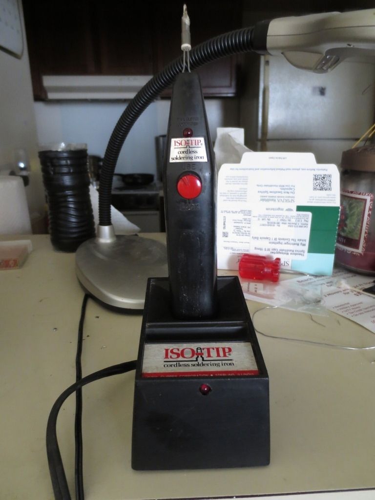
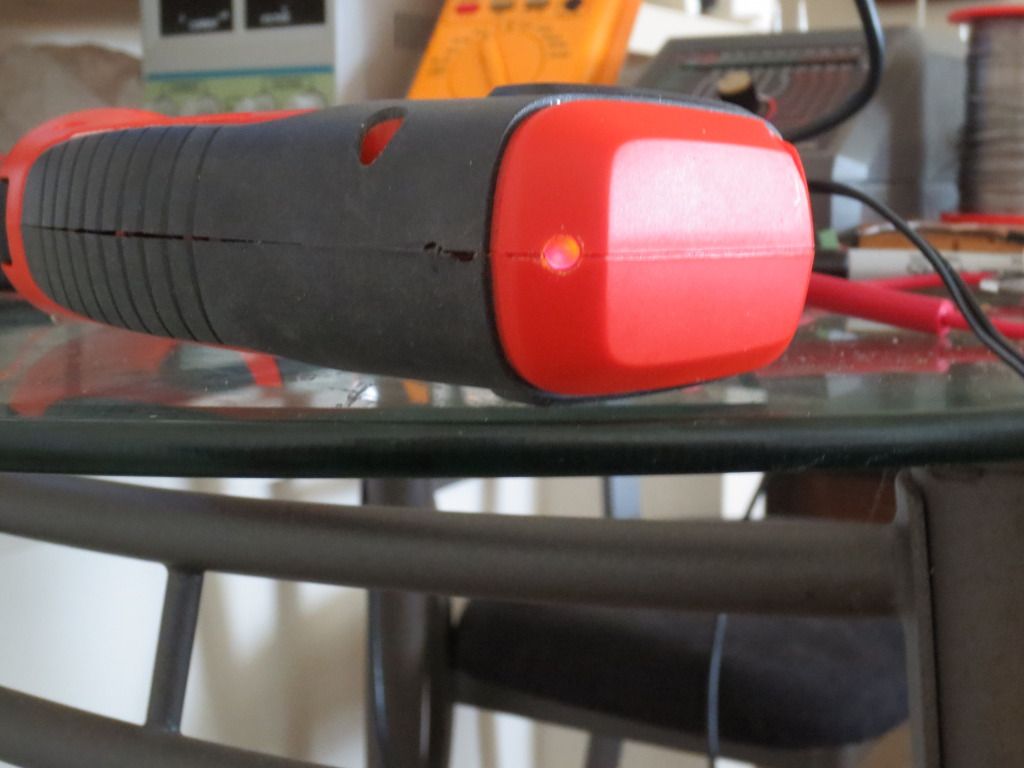
Years ago I had added an SCR LED circuit to the base to indicate when the batteries were charging.
When the iron is first placed in the base, the red LED goes dark or dim when the iron makes proper contact.
Eventually the LED gets brighter when the batteries are drawing little current.
I happened to have a pair of Nimh 1.2 volt, 6000 mah tabbed rechargeable batteries so I replaced them
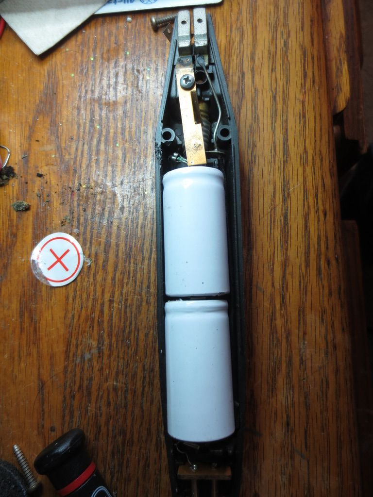
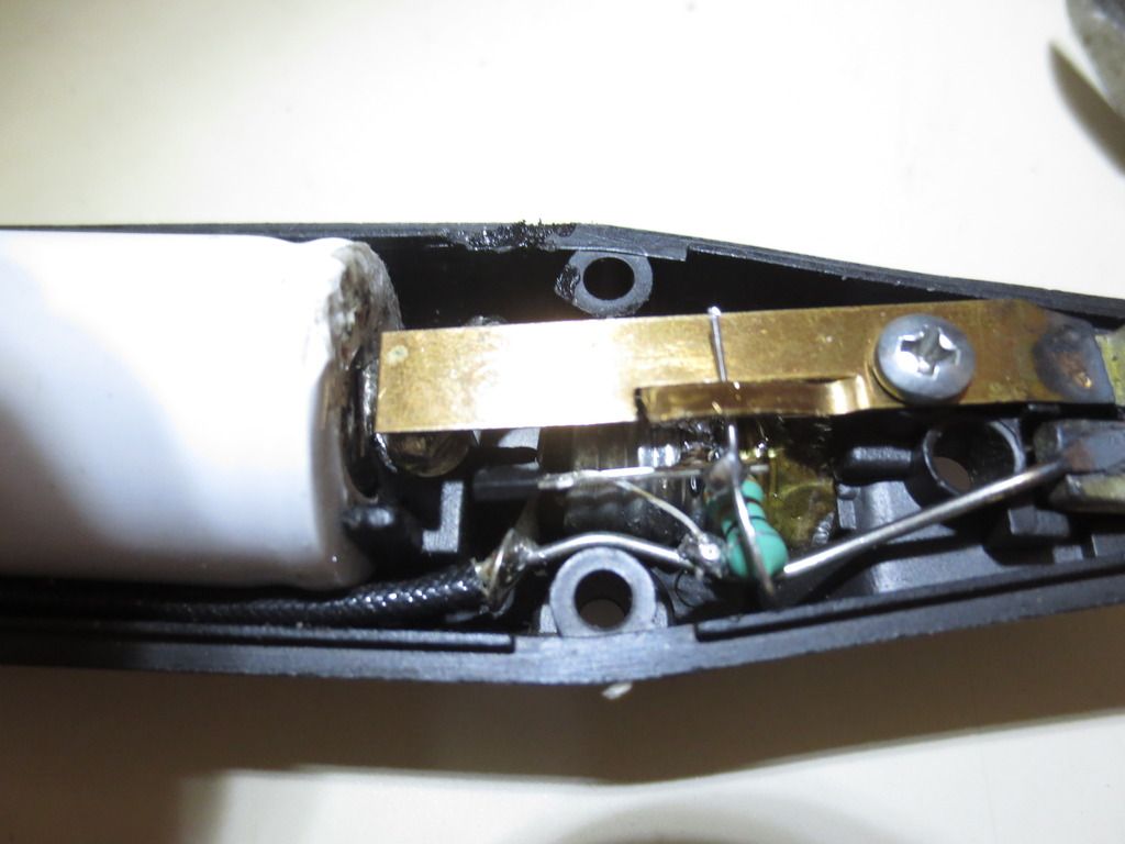
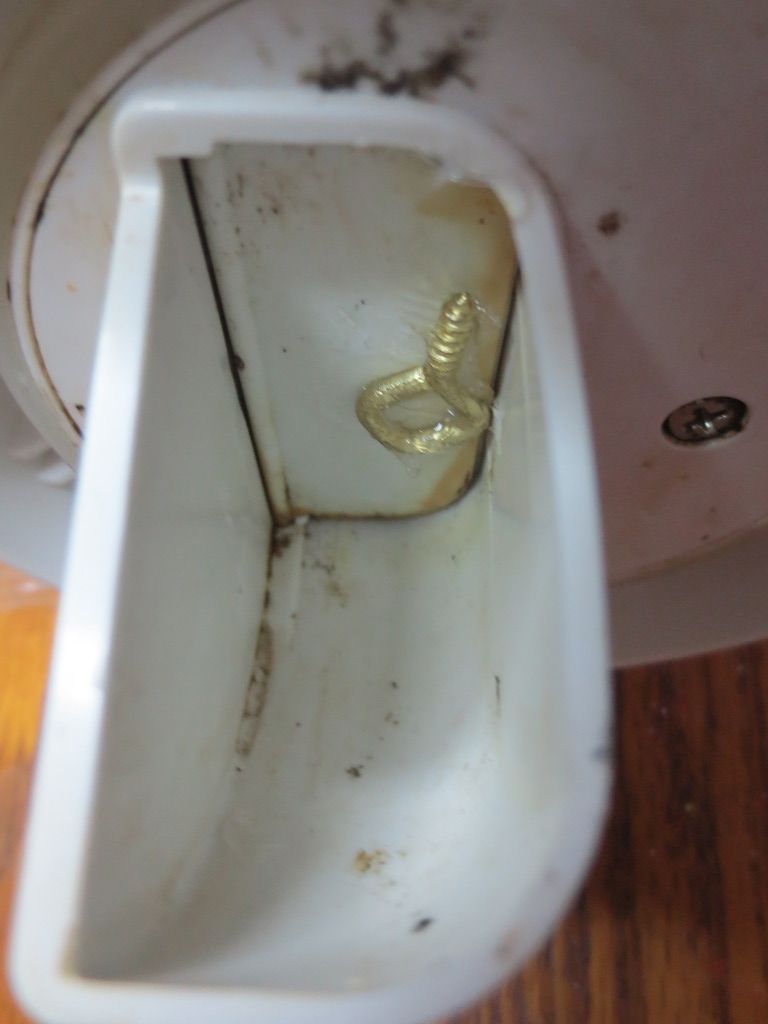
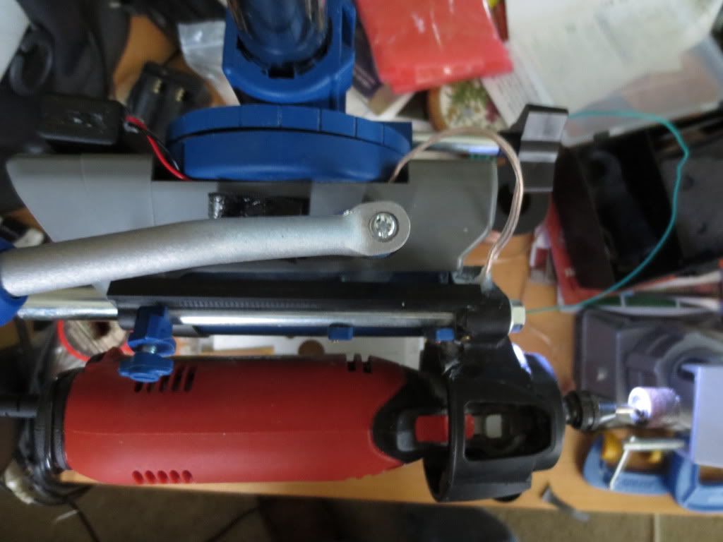
The large copper plate is pushed down to the + battery button on left to heat the tip and light a lamp.
The lamp gets positive voltage from the copper plate to the side through the bent down tab originally.
The button on left can be unscrewed using needle nosed pliers. I enlarged the + tab hole with a rotary tool.
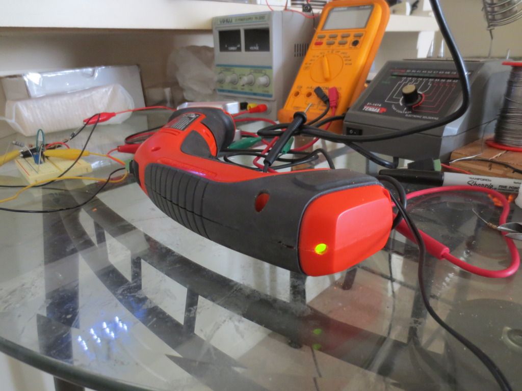
After recharging the new batteries, I noticed how dull the lamp was compared to a 10 mm bright LED.
The lamp uses .27 amps or 270 milliamps while a simple coil Joule thief circuit uses .04 amps or 40 ma or less.
Problem is that the batteries need to deliver 3 volts, but both only give 2.5 volts max. Needs a Joule thief:
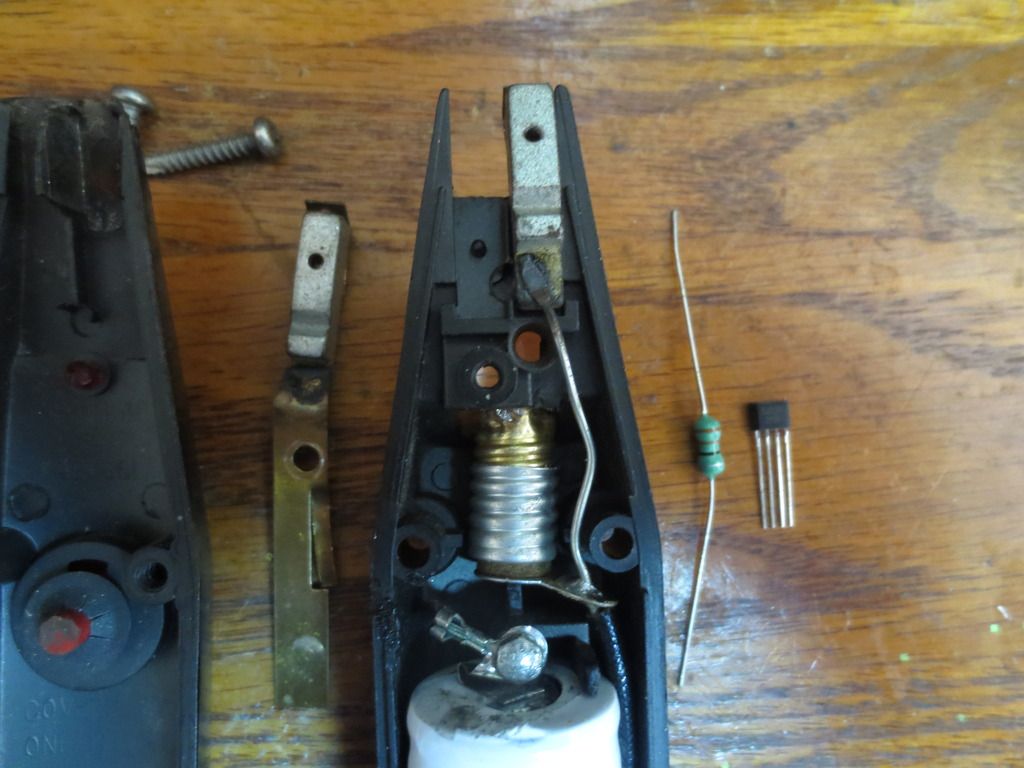
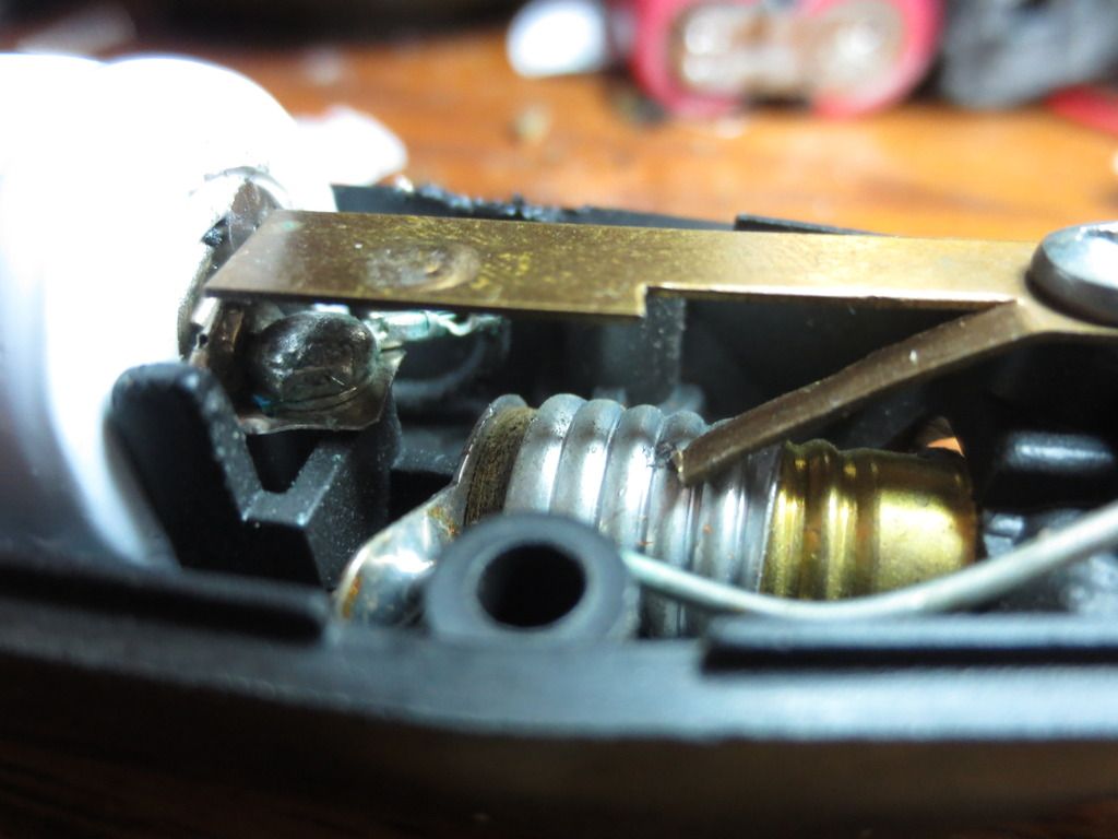
The 5252F chip and a 33 uH coil on right needs to be added to the soldering iron so I removed the button plate.
NiMH denotes the battery required, one or two 1.25 volt rechargeable or 1.5 volt regular batteries.
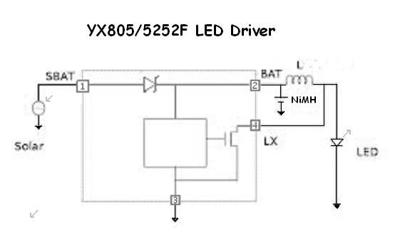
Do NOT use regular batteries in rechargeable devices!. Pin 1 is used for solar or low +DC charging voltage.
Chip pin 1 is unused and cut off. Pin 3 needs bent back and soldered to the negative bus on right first.
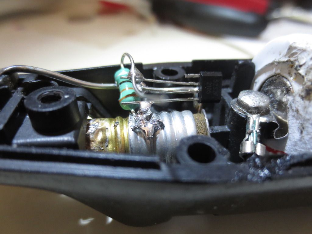
Pin 4 and one end of the coil go to the + side of the lamp base as the bulb bottom is wired to negative bus.
Pin2 goes to other end of the coil and plate. After straightening the lamp tab, the coil wire slid right in.
I didn't even solder the pin 4 coil wire to the plus button plate. It could also have been run to the plate screw.
I broke the old lamp and put a 10 mm white LED in the socket with anode to side and cathode to bottom.
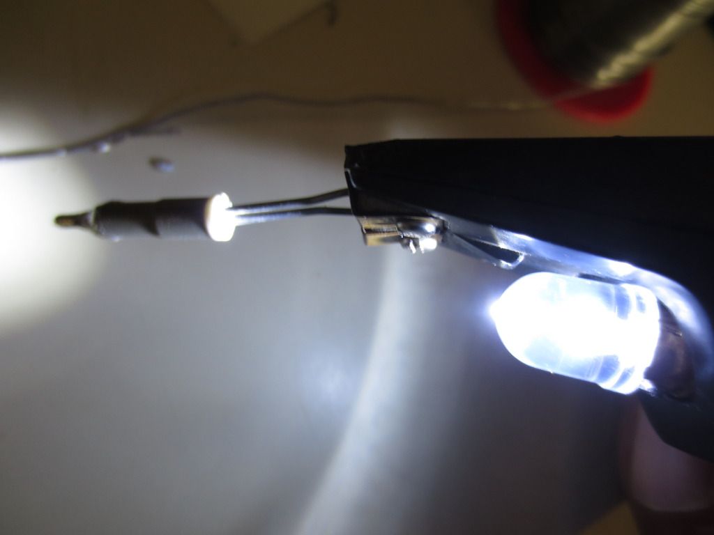
Now I can actually see what I am doing 10 times better using one tenth of the soldering tip current to do so.
Statistics: Posted by burger2227 — Sat Feb 18, 2017 12:26 pm
]]>
This clear bright LED worked the best against other translucent types. Even when brighter than originals.
Here's the old LED:
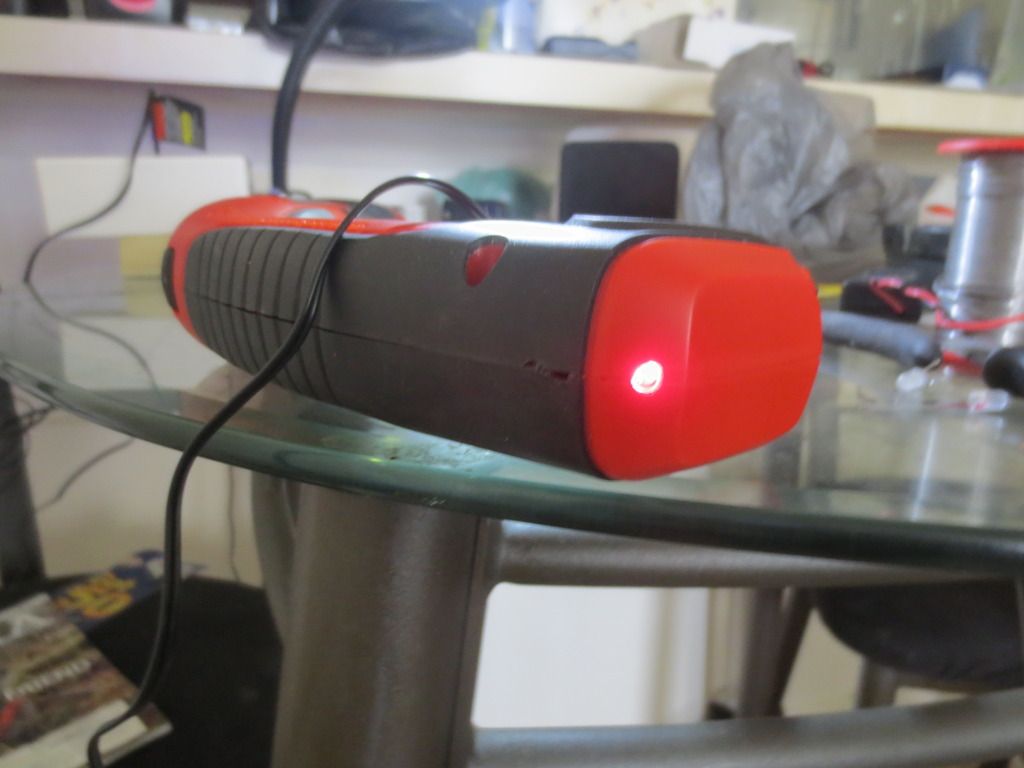
The charging status stayed red for 2 or 3 hours and I started wondering about the batteries:
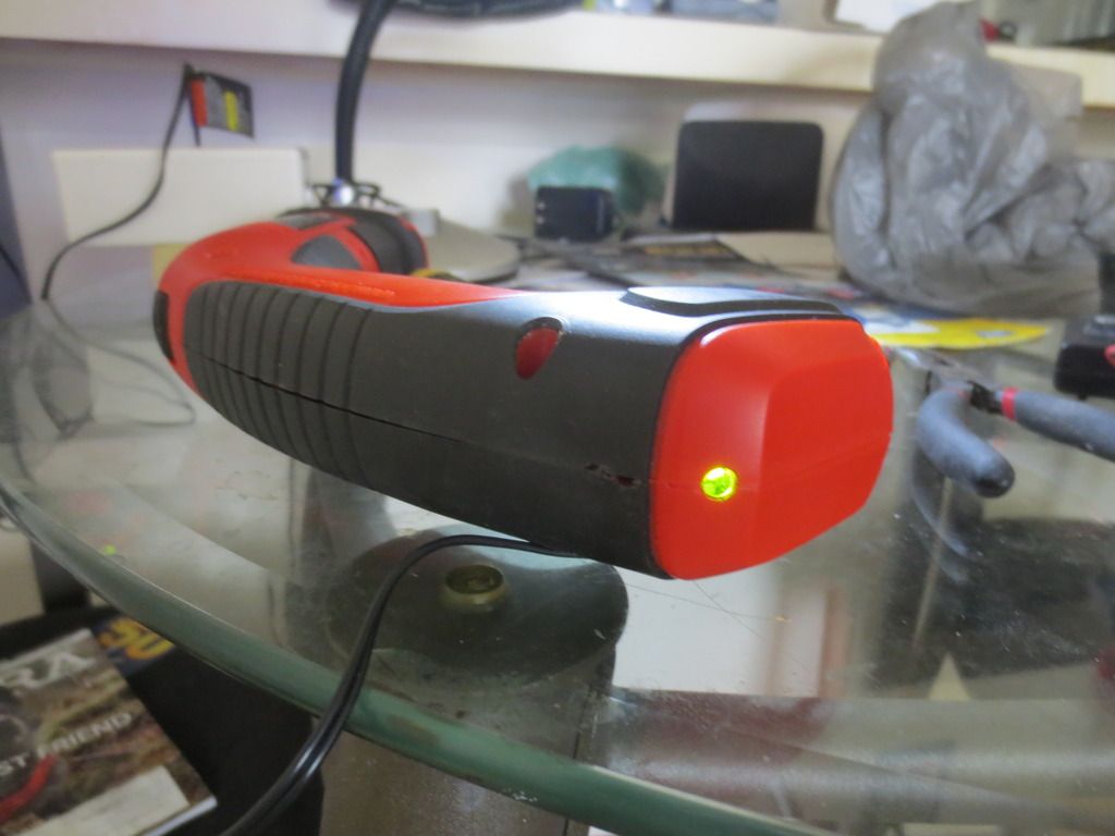
Suddenly it turned green with less of the mixed red and green mixed effect before that.
The old bipolar 2 pin LED was similar when green :
Monitoring battery charging. Rectified + charging voltage is compared to battery voltage
separately so that the LED will only light while charging and not drain the battery.
Also you may want to use a larger value trimmer or add a switch to cut off all drain from the
battery if tool is not used often. A 100K trimmer's current draw is .06 milliamps per 6 volts.
A small relay on the charge voltage could also be added to disconnect the battery fully.
Since my drill charges a detachable battery pack, I have to charge through the drill and remove.
I will add a charge outlet and perhaps a monitor to the battery packs when I convert to Lithium.
The Zener diode's voltage rating should be about half the battery voltage being charged.
This circuit uses a 2 pin bicolored or bipolar LED wired so that it is red when the voltage drops
below a certain voltage and turns green when the voltage is higher. The LM741 Op Amp
output pin 6 goes high when the voltage is higher and low when the voltage is lower.
I found that bad NiMH batteries go green pretty fast when they can no longer hold a charge!
I compared two drill battery packs I had and the newer one took hours instead of 15 minutes.
I will be attempting to make a 12 volt NiMH pack into an 11.1 volt lithium soon I hope.
My B & D Dust Buster is going south so stay tuned...
Statistics: Posted by burger2227 — Fri Mar 11, 2016 1:41 pm
]]>
The flap would get stuck open at times and bugs or dirt would fall out when hanging it up. It can't stick up now either.
I found a small hardware hook that added some weight to it when I pasted it to the inside of the flap keeping it closed.
I used my famous clear silicone calking too! It should hold as good as a glue gun would.
The NiMH or NiCad batteries are getting worn out already so I may be following this up with a Lithium battery upgrade soon!
I have batteries and a special charging circuit ready to change it over from 12 to a 11.1 volt Lithium setup.
It should last a lot longer. I also have a charging set up that will stop charging it with LED red to green indicators I may add too.
PS: Dust Busters are great for cleaning up roaches and other big crawling bugs without smashing them!
Statistics: Posted by burger2227 — Fri Aug 14, 2015 2:35 pm
]]>
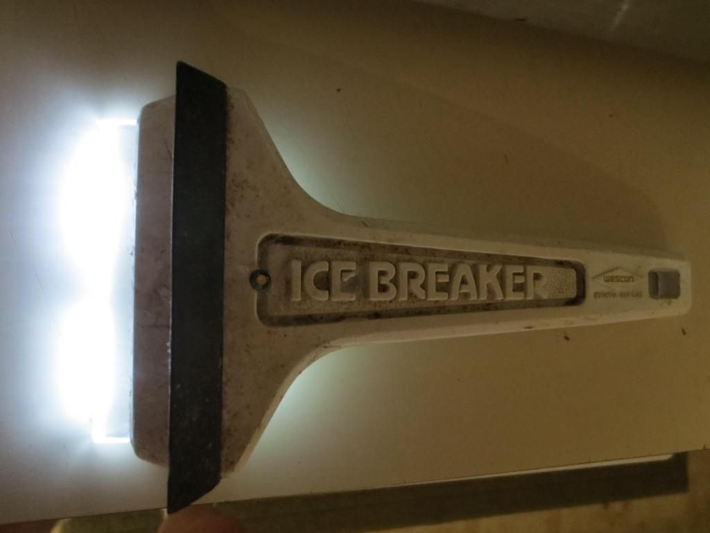
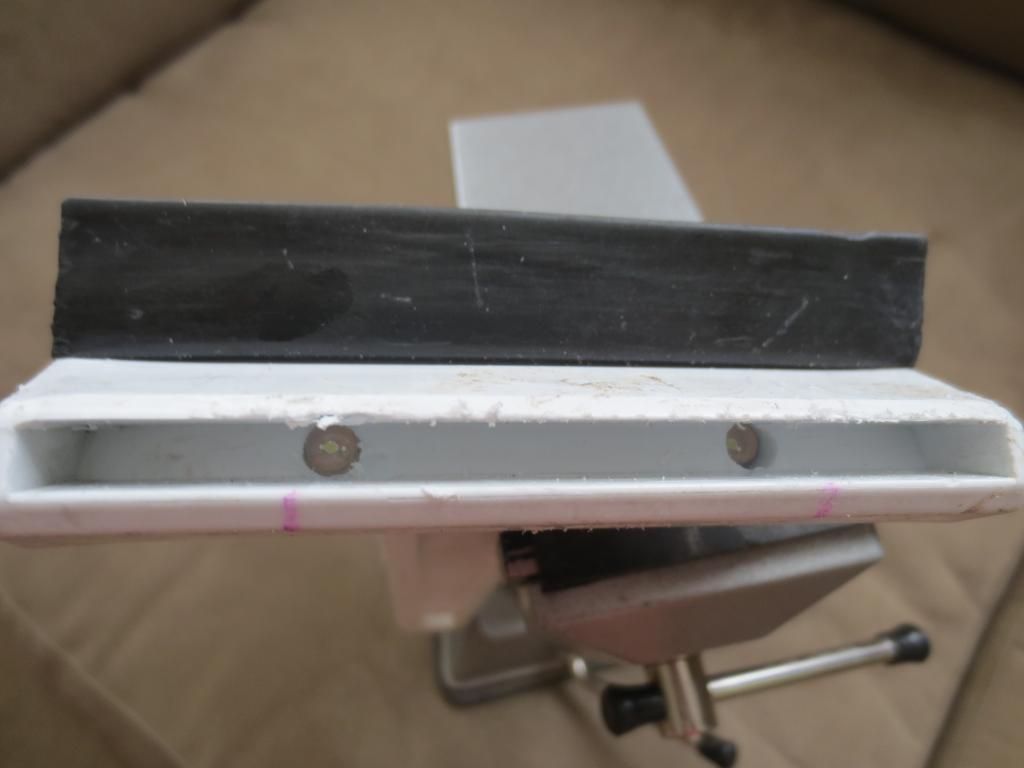
As you can see it has been well used over the years. I was surprised I could even pull out the blade.
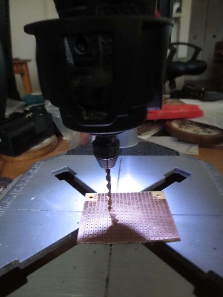
Removing the blade allowed me to drill 2, 1/4" holes for flat top LED's behind it. The holes came out behind the rubber squeegee on the bottom side:
The circuit uses a tilt switch (similar to a small electrolytic capacitor) that turns on the LED's when the 2 leads are facing down.
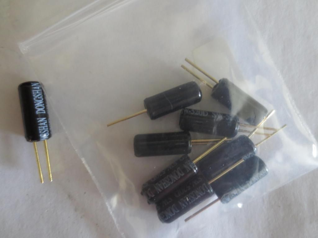
Each small tilt switch canister holds a metal conducting powder that completes a circuit when oriented correctly.
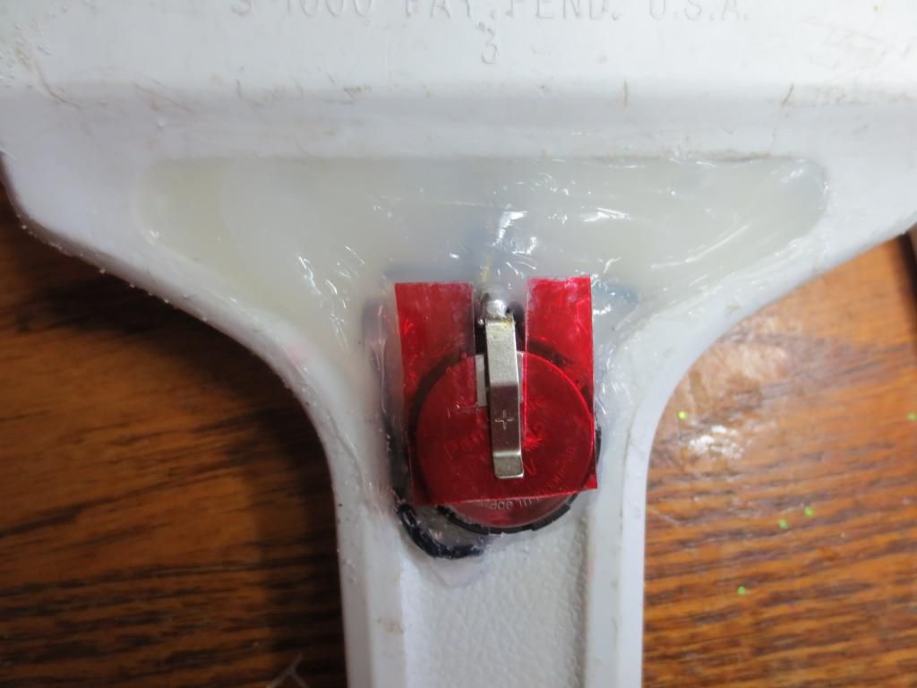
I drilled a 1/4" hole through the handle to hold the canister. The two bottom gold leads are shown below the battery holder:
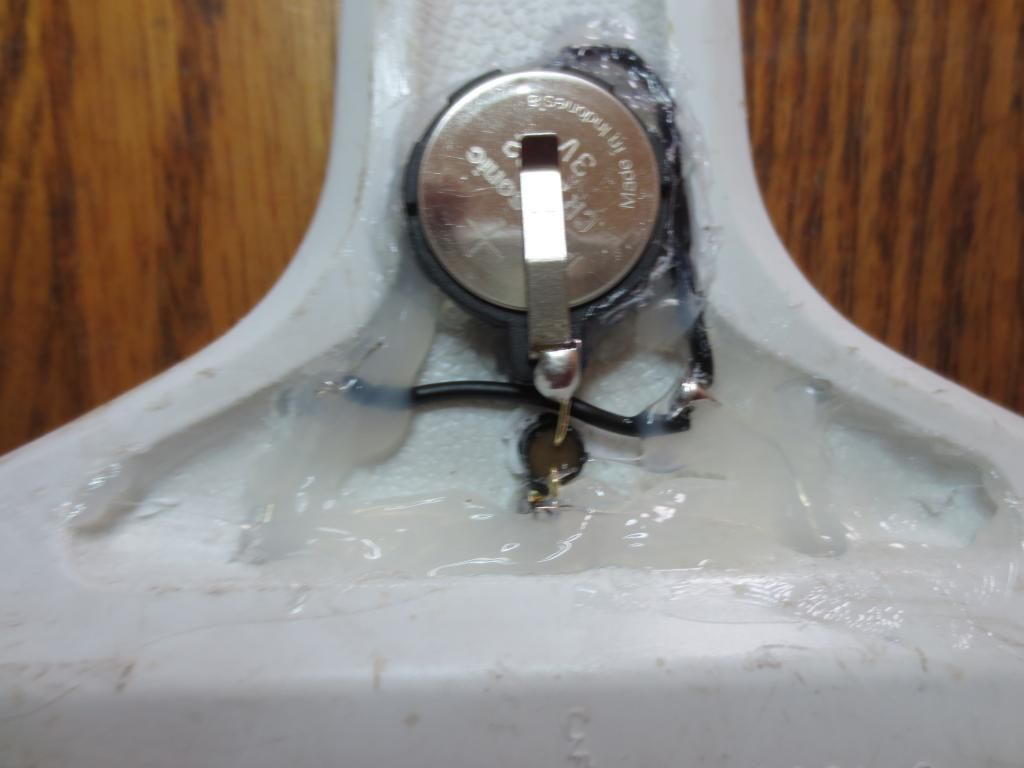
One lead goes to the LED positive anodes and the other goes to the positive 3 volt CR2032 battery. The black wire goes to both LED cathodes from the negative battery.
Once everything was wired correctly, I hot glued the battery holder in place and covered up most of the wiring with clear silicone caulking:
Time will tell how the battery holds up! I just have to remember to keep it laying upside down...
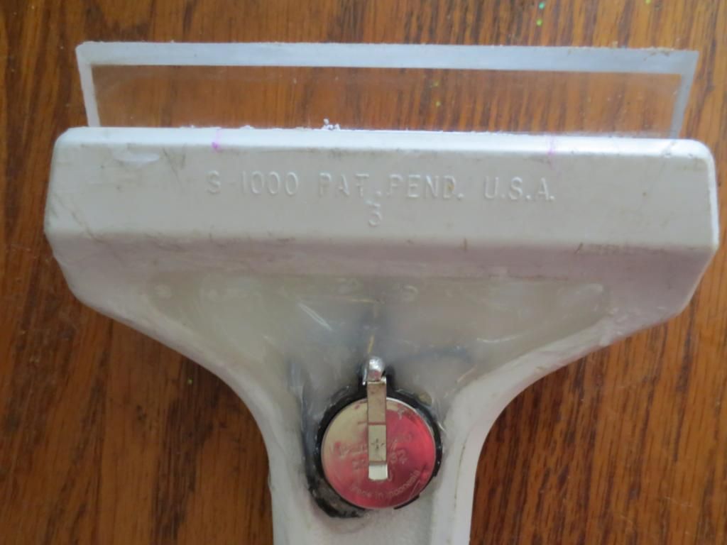
Or with this kind of battery holder, a simple slotted square of cardboard or clear waterproof packaging can be used to cut off power:
There are also CR2032 holders that are completely enclosed and have a small on/off switch available on Ebay.
Just slide it forward when light is needed. The positive battery clip keeps the power cover from turning and falling off:
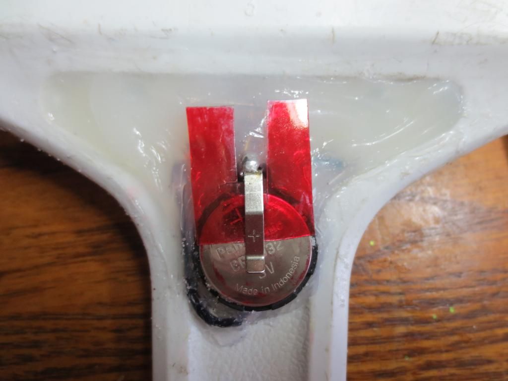
I painted the clear packaging with permanent red magic marker to make it stand out. It could also eliminate the need for the tilt switch.
Statistics: Posted by burger2227 — Mon Dec 15, 2014 11:14 am
]]>
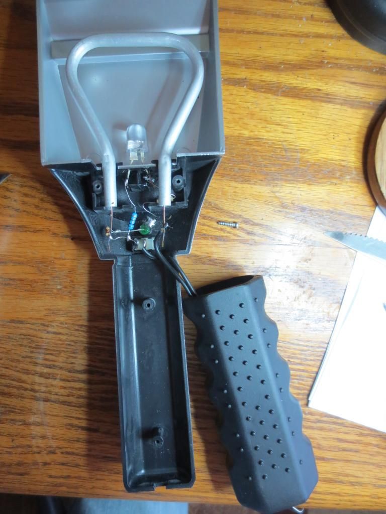
I found 2 screws in the bottom and 2 more after I slid the handle grip off. It was a simple matter to add a 10 mm LED.
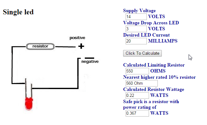
The math for current is simple 14 volts - 3 volts = 11 volt drop / .020 = 550 ohms
At 20 ma current I needed 560 ohms resistance with a 3 volt LED on 14(alternator) volts: http://www.quickar.com/noqbestledcalc.htm" target="_blank
I drilled 2 small holes with a rotary tool for the LED legs and soldered a 470 ohm resistor to the positive anode and 100 ohm one to the cathode side.
The 10 mm LED should give plenty of light now for using it at night or in the early morning and it can also sub as a work light:
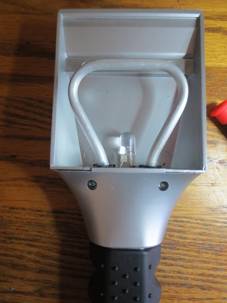
The hollow handle has plenty of room for a single battery 5252 chip circuit to run the LED after the heater coil wears out too!
Here is the new blue LED light:
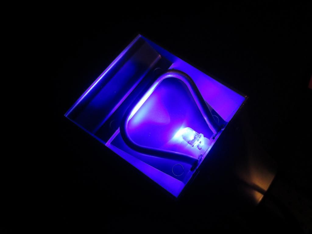
Here is the blue light on a window. Later I put clear silicons calking on the LED legs to block water from getting inside of the handle circuitry.
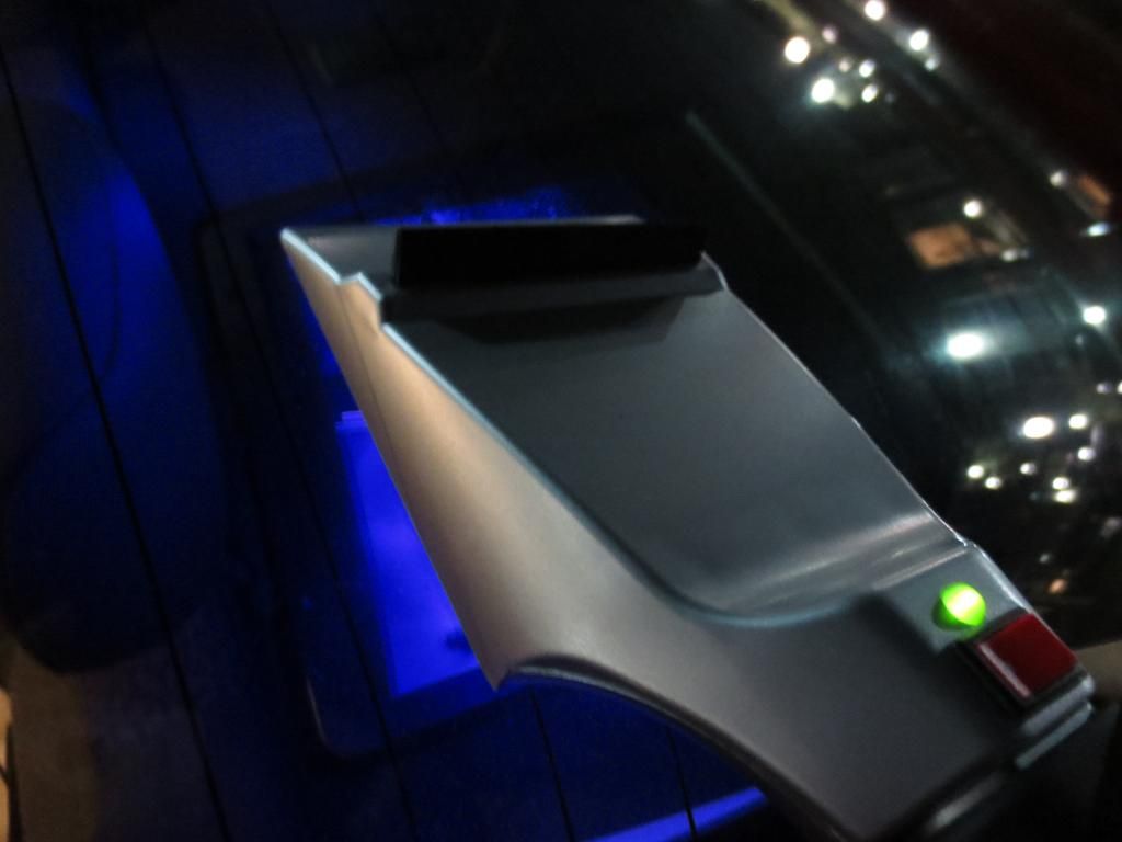
The heater coil gets quite hot! Hot enough to burn you and it takes a while to cool down after it is turned off! Could burn seat fabrics too!
Statistics: Posted by burger2227 — Sun Dec 14, 2014 12:47 pm
]]>
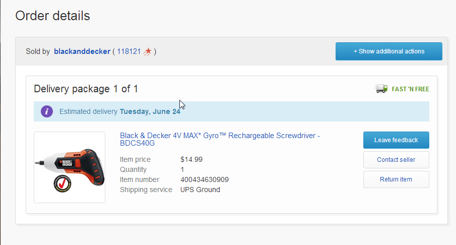
It even has an LED light and turns screws the direction in which it is turned.
A day later the price had increased exponentially:
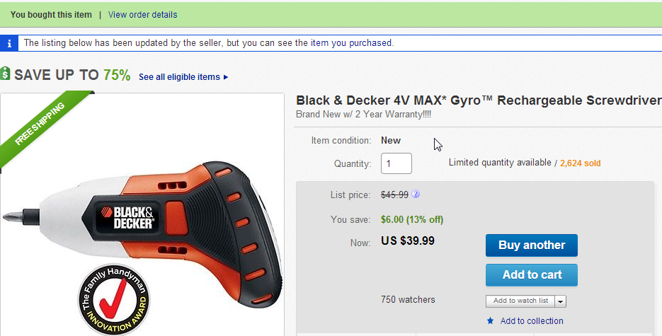
The screwdriver turns the direction it is leaned to. Left is CCW loosening and right is CW tightening.
The instructions say that the battery can be removed by simply tearing the cover apart and removing the connector wires:
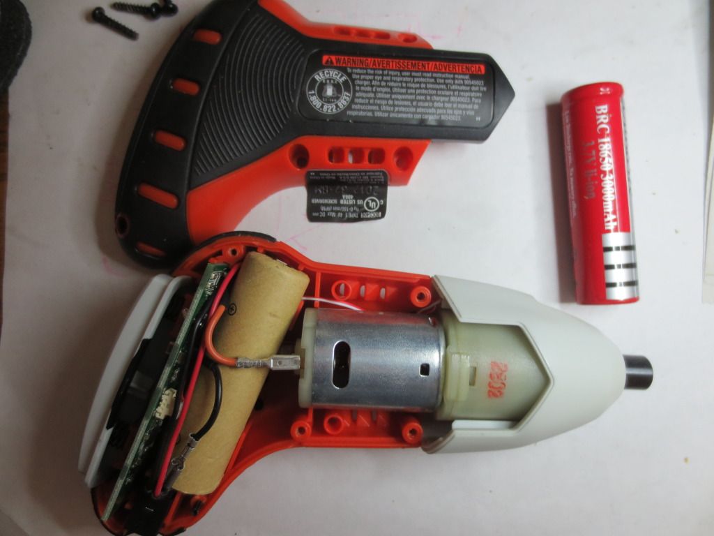
The battery is a tabbed 18650 3.7 volt lithium ion similar to the one shown on the right. B & D says to remove it when you throw the driver away.
I have a funny feeling that I'm gonna replace that battery some day. Hopefully not for another 10 years!
The large white button on the left activates the driver when pressed. The more the unit is turned to the right or left, the faster it turns.
Note: The cover has a label on the bottom that may void the warranty if not peeled off carefully.
The LED never shines on the bit and the trigger button must be pressed to light it up at all! No way to see anything in the dark:
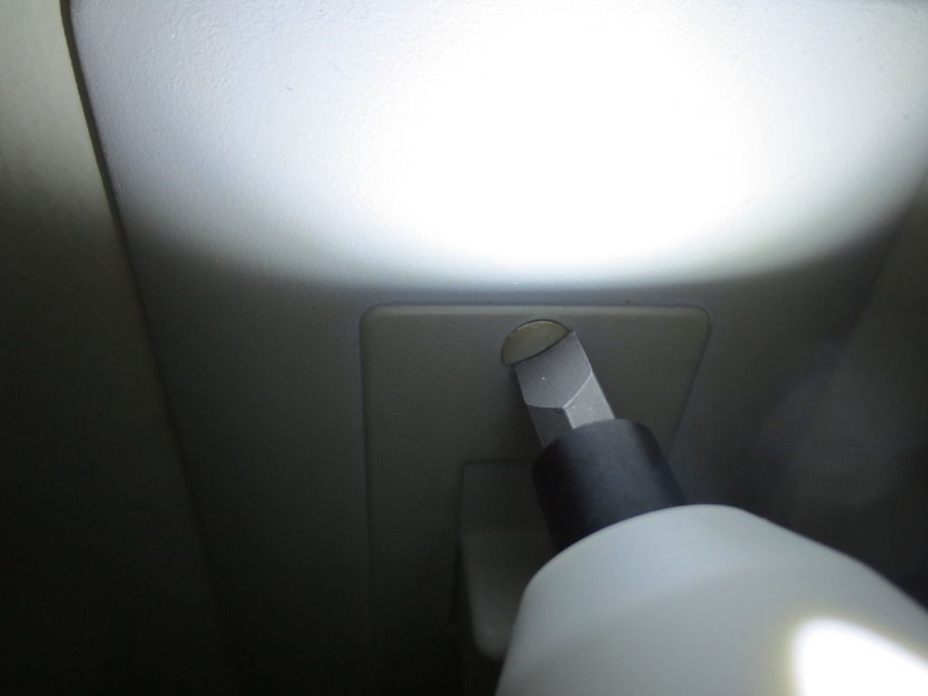
No matter how gently I pressed the trigger button, the bit would turn when I tried to just turn on the LED to spot the job.
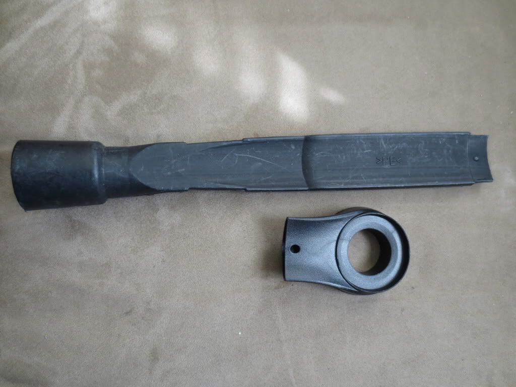
The wall charging unit uses a special 3 pronged plug in the bottom of the gyro driver handle. There is no power or charging indicator.
The unit is supposed to flash the LED when the battery gets low or flash twice when the gyro is reset. Pressing the trigger button quickly
while the unit is laying on a solid surface resets the gyro direction settings if it gets too far out of whack.
Statistics: Posted by burger2227 — Mon Jun 23, 2014 11:31 am
]]>
I decided that I could use one of them to suck up dust from my rotary tool when using the grinder or sanders.
The vacuum tool end needed some metal to hold the tool on the work station at any angle with magnets:
It took a few attempts to create a metal ring out of the ends of tin cans. To drill out the center hole first, I used a
pointed one inch hole saw drill bit and drilled down into the end of the can very slowly. Drilling too fast would destroy
the can end or cause serious injury! After the center opening was done, I put the can into a can opener and used
scissors to cut out the outer circle. I had to cut the outer edge very carefully to get a tight fit in the vacuum tool.
Next I arranged 4 magnets around the work station holder cup bottom using super glue to hold them in place:
The magnet center holes help hold them in place.
Here is the final assembly with the attachment hooked to a vacuum hose. The magnets hold it on pretty well:
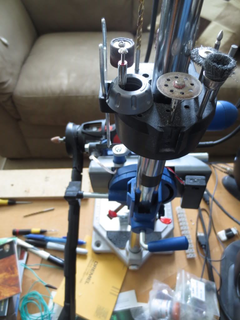
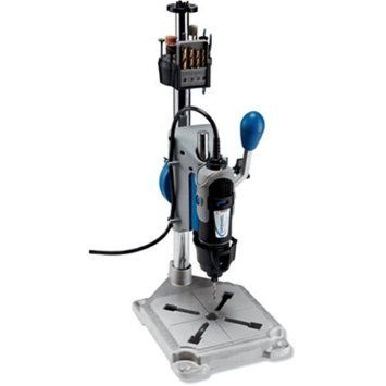
Note the Dremel Work Station "crow's nest" that holds all of the rotary tool attachments too.
The vacuum tool end was completely open, limiting the vacuum's suction power so I added a cardboard center ring to it too:
The cover helps increase the suction at the outside edges and keeps dust off of the tool and work area.
I don't know how I endured not having the rotary tool work station so long! It makes projects so much easier!
Statistics: Posted by burger2227 — Sat Mar 22, 2014 9:34 am
]]>
I was able to fish the clear wire through the back plate and solder the wires, tape them and hide them inside the back.
I had to drill a hole in the side of the battery holder to reroute the wires so they were not in the way of the switch on that side.
A 5252F LED driver chip with a 33 uH coil is supplying 30 ma from one AAA battery to the parallel LED's. Each uses 15 milliamps:
The LED's light up the work piece all the way down when using the press. It is nice to not have to push a drill and try to
stop it after it goes through the work. Inertia causes a lot of drilling errors and injuries!
On another note, I found some new bipolar red/green LED's that are brighter red than the old one I was using on the right:
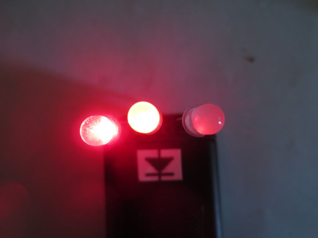
The fact that all three are lit also tells me that they all use similar voltages. Otherwise the lowest voltage one would light.
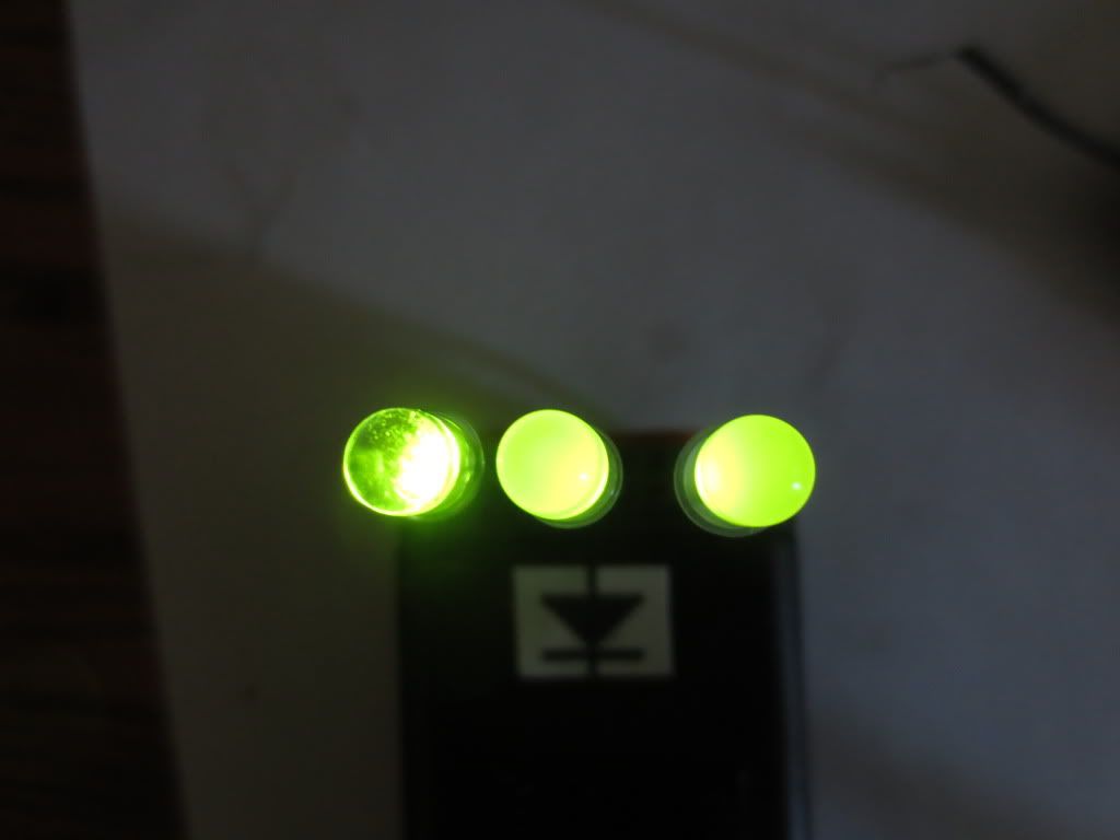
The LED on the left is clear and bright while the center one is diffused like the old one on the right. Green looks good on all three.
The sellers from Hong Kong say that they are flashing LED's, but the polarity must be reversed to get them to alternate colors.
The long leg on positive side produces red and positive voltage on short leg produces green while the other leg is common.
I plan to try the middle one on my drill charging status circuit because the red is barely visible across the room.
Hopefully the LED voltage required will not affect the charger monitor circuit's Op Amp performance.
Statistics: Posted by burger2227 — Tue Feb 25, 2014 1:45 pm
]]>
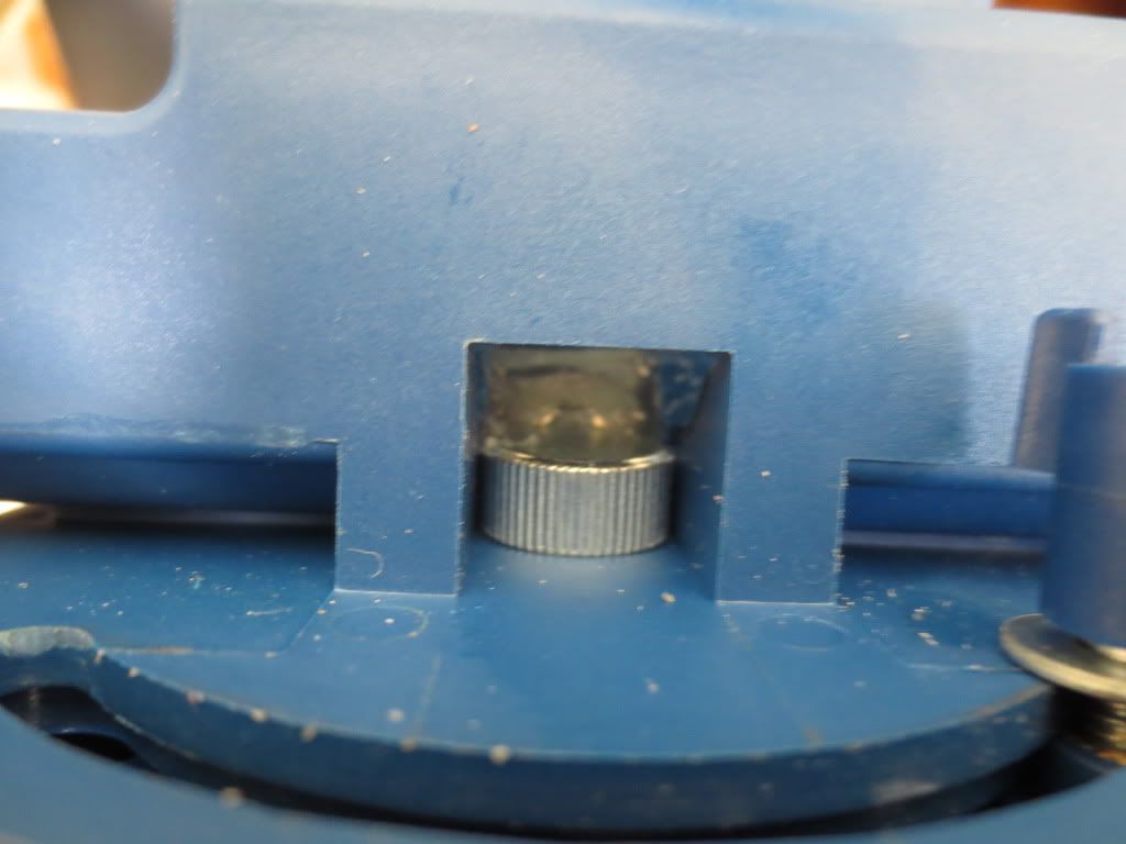
I took this picture after I dabbed silicone calking all around the square nut to hold it in place. It is tilted to the left
because it is tightened fully. The main press shaft blocks access to it also when assembled.
Here is a look inside where the rotation lock nut is on the upper left and the up and down lock nut is on the right:
I added silicone to both sides of the square nut in the slot on the right to keep the nut in place instead of falling out.
Testing both by removing the bolts completely had mixed results. The rotation lock nut was still hard to re-thread.
I am also preparing a switched AAA battery holder for the LED work lights. It will be held to the unit with Velcro.
Statistics: Posted by burger2227 — Mon Feb 24, 2014 1:57 pm
]]>
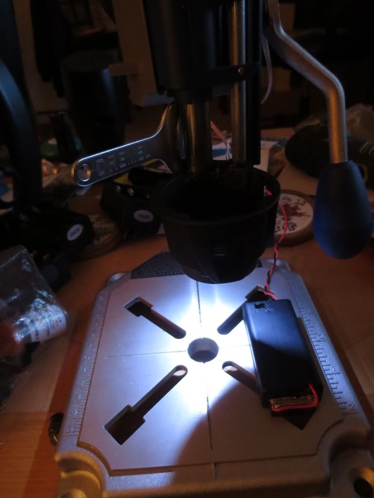
So far I have just wired up the 2 LED's without a battery holder, switch or driver circuit. The cup nut tightening wrench
is holding the assembly down for the picture. My LED tester is driving the circuit for the time being while I wait on a battery holder.
Here are the two LED's mounted in the rear of the cup aiming as far forward as possible:
I used clear speaker wire to run to the battery and driver circuit to be mounted up above
Now I have to get a AAA battery box with a switch that will fit up above.
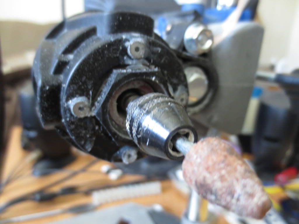
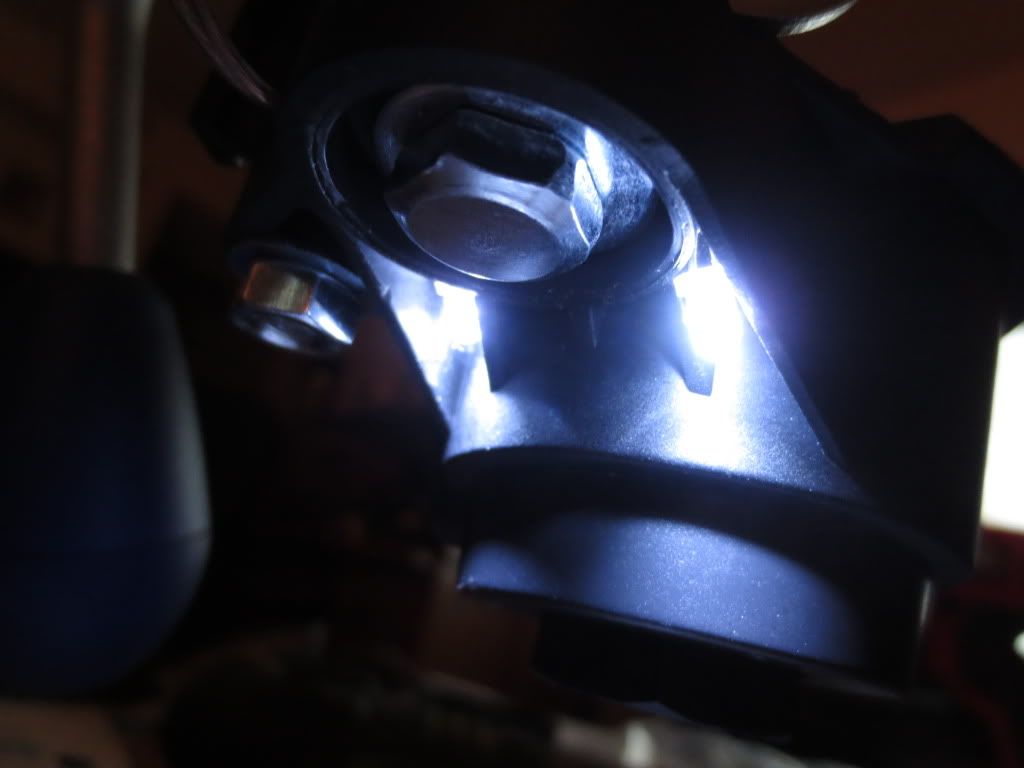
Here is the work station rotated to work as a grinder. Note how the LED work lights light up the small stone:
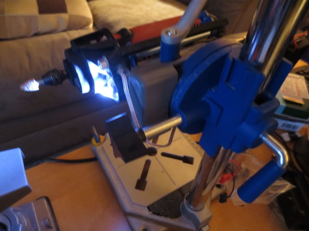
It is a lot easier to grind things with the object in your hands than holding the tool in one and the work in the other!
The LED battery pack rotates with the tool holder assembly too. Now I won't have to hold that rotary tool when it
gets hot either. I used to have to put it down when it got too warm. I think I'll leave it there.
Statistics: Posted by burger2227 — Thu Feb 13, 2014 6:52 pm
]]>
I figure it might also come in handy as a third hand as the holder can also hold it sideways for grinding.
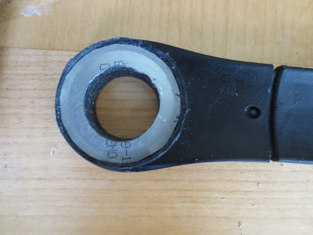
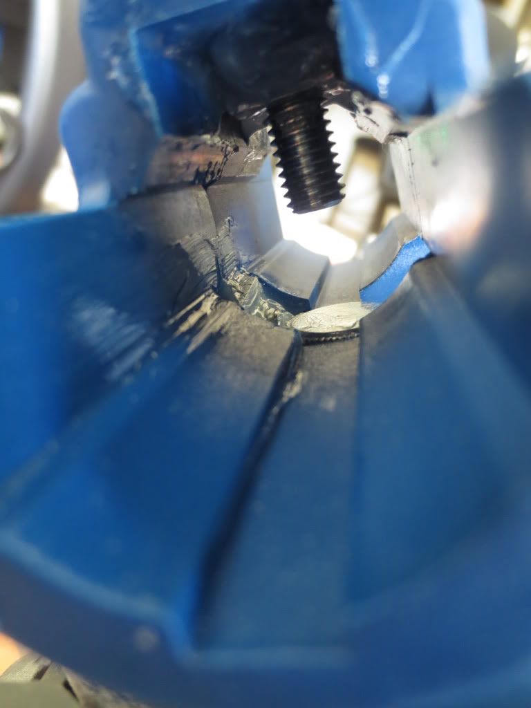
While putting it together I noticed a lot of play in the mounting cup area where you stick the tool nose:
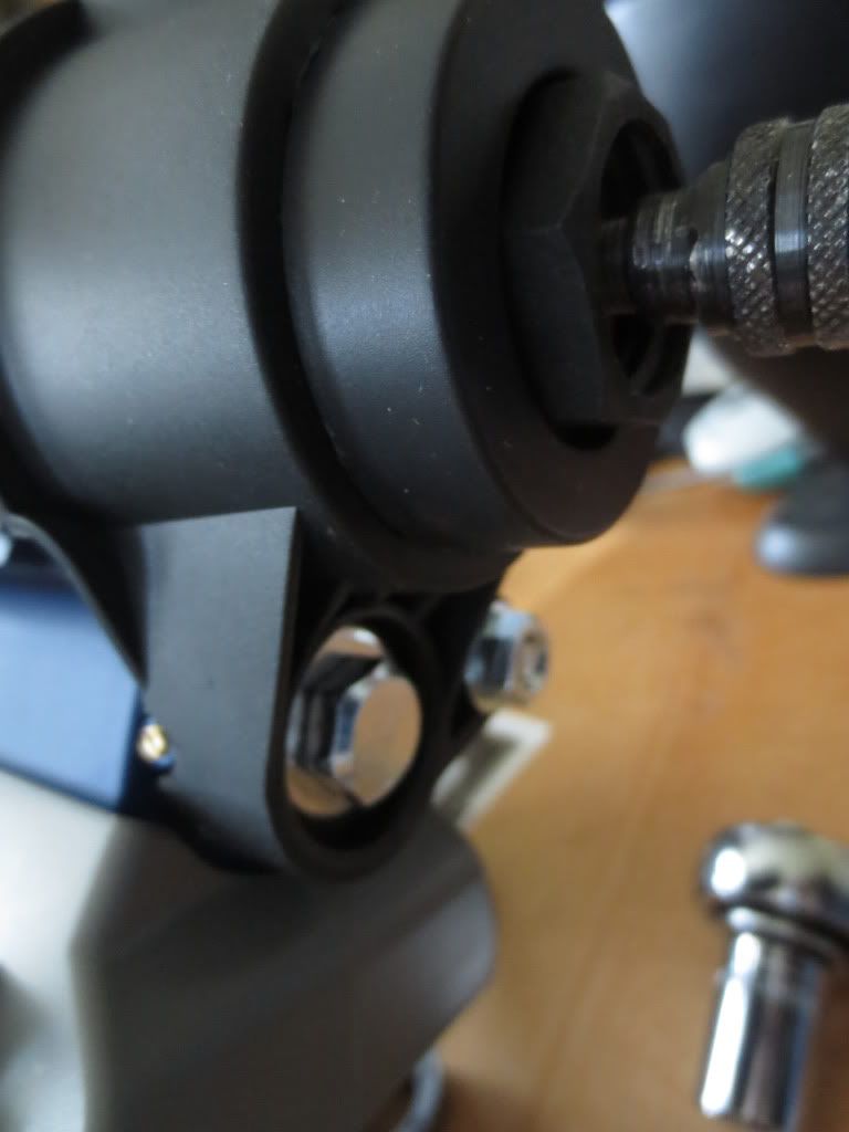
The large bolt was loose so I tightened it up with a 13 mm socket on a ratchet. Now the tool only moves down
when I push on the lever. Those cavities next to the bolt look great for LED work lights too! Hmmm...
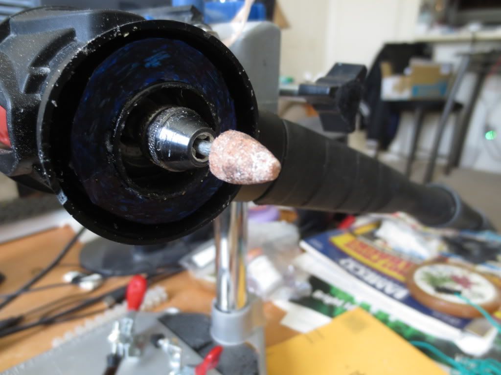
My B&D MTX3S rotary tool screws right on to the mounting nut in the cup, but I had to turn it sideways for the cord boot:
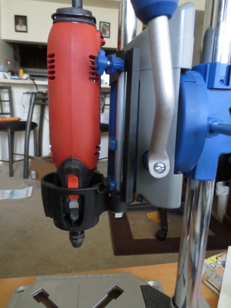
The grey shaft lock can be flipped up in the cup opening and the orange power switch can be slid up and down
with a little effort. The tool also uses a Dremel keyless chuck that allows use of drill bits and different size accessories.
Statistics: Posted by burger2227 — Wed Feb 12, 2014 7:40 pm
]]>
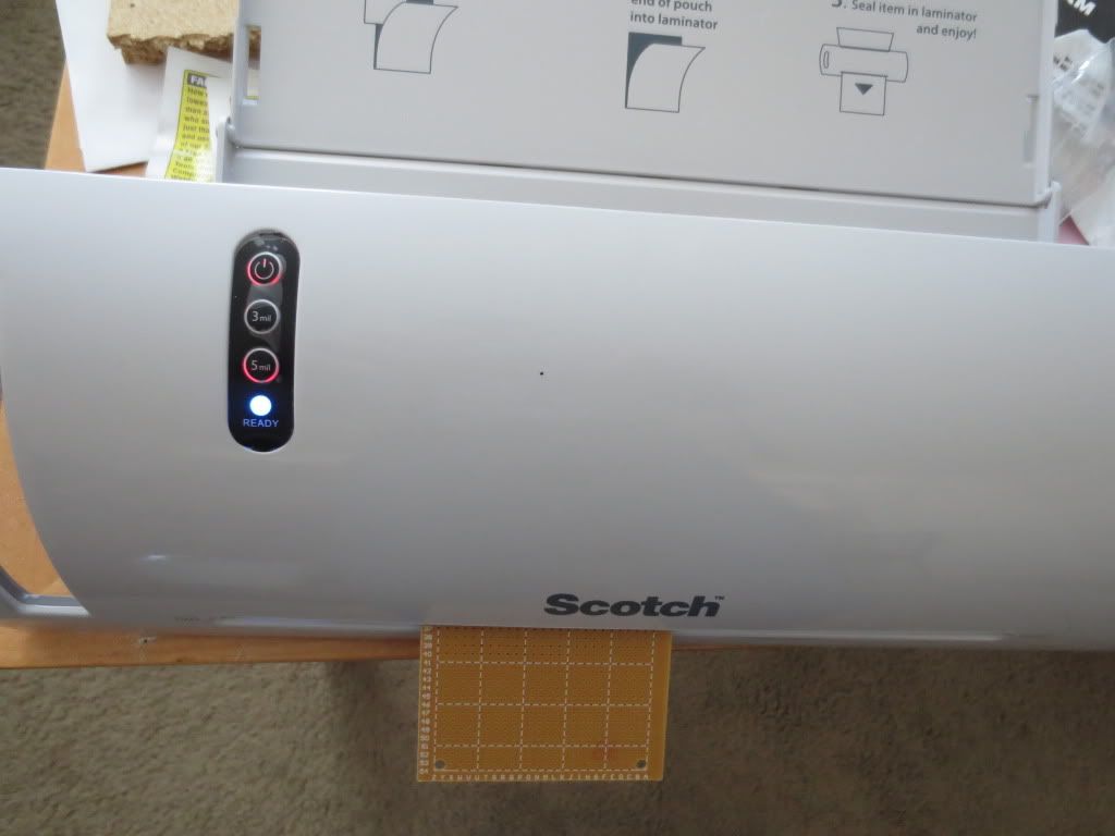
Printed circuit boards can go right through! After 5 or ten passes, the board was up to 120 degrees.
Here is the laminator with the cover removed. The circuit board plug has to be removed on the left
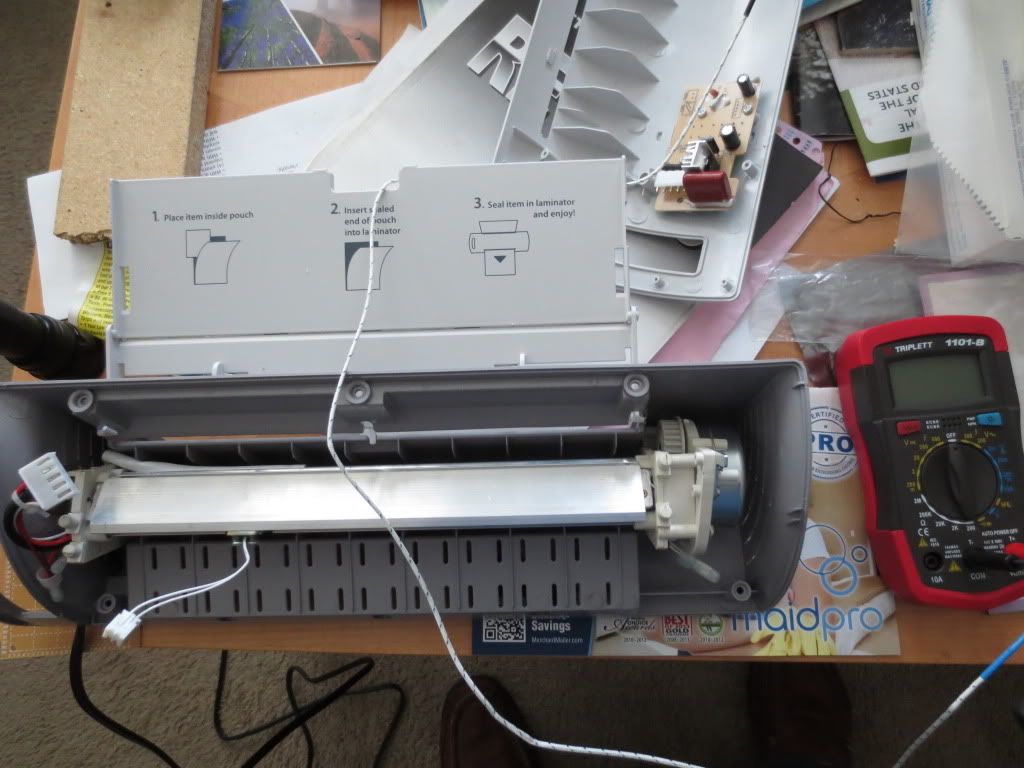
The entire roller and heater assembly lifts out if something gets jammed. The roller motor on the right is 120 volt and only turns CCW.
The rollers start turning as soon as the unit is turned on. Same with the heater, but you have to wait until the blue LED says Ready.
The control circuit board looks pretty simple. Just a pair of 600 volt triacs, a heatsink and a 250 volt capacitor:
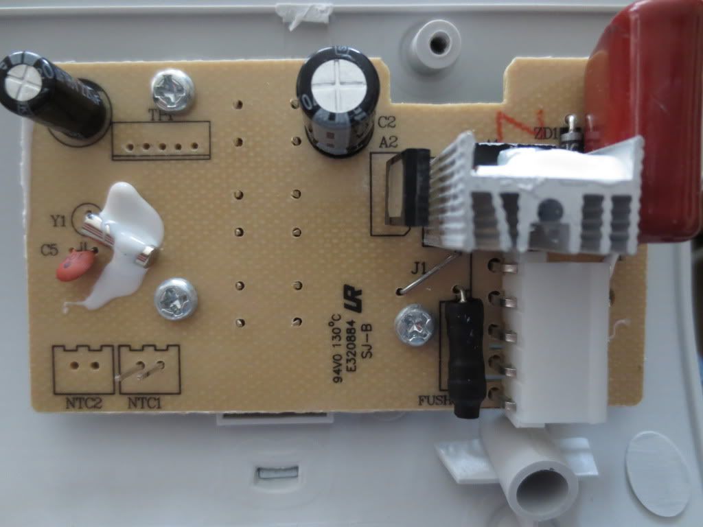
The capacitor says 225K which converts to 2.2 uf or 2,200,000 pf. Another cap power supply for what? What's the silver crystal resonator for?
A lot of stuff on the back apparently! The capacitor voltage is rectified and set to 5 volts with U2, a 78L05 voltage regulator.
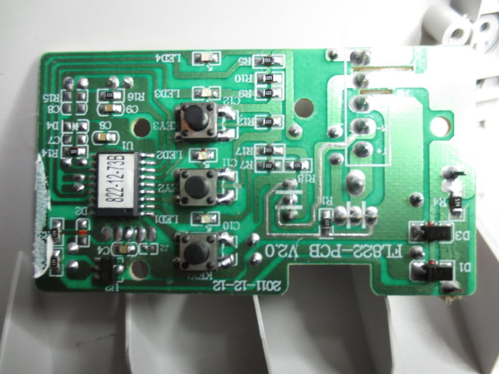
It doesn't use a lot as the 78L05 is only rated for 100 ma current.
The release lever on the right side can disengage the motor from the rollers when something gets jammed, but it
can also be used to stop a circuit board until it gets hotter perhaps. Pulling things out of the unit was not very easy!
Statistics: Posted by burger2227 — Sat Feb 01, 2014 12:57 pm
]]>
I had the same problem a while back and had to fix the DMA settings. Do the following:
1) Go to Control Panel\Performance and Maintenance\System\Hardware tab to Device Manager button.
2) Find IDE ATA/ATAPI controllers and click it to drop down the Primary and Secondary IDE channels
3) Right click the Primary Channel and select Properties from the menu. In advanced settings tab it should have DMA if available
selected with the current DMA status below. Do NOT select PIO only!
If the hard drive status says PIO, the only thing you can do to reset it is Uninstall it! Right click the
Primary Channel again and select Uninstall. It will ask to reboot immediately so allow that too.
This may sound harsh, but the computer will reboot and re-install the drive hopefully with DMA access.
After it re-installs the drive, it may want to reboot again so let it reboot and check the Primary Channel status again.
The same procedure can be done with the Secondary Channels that hold the CD and DVD drives.
Statistics: Posted by burger2227 — Sun Jan 26, 2014 12:23 pm
]]>
To make the fan guard, I just used the clear plastic packaging and cut out a cross. Taped it to the front panel
with the mask removed and sandwiched the guard with the mask. You can barely see it!
I cut out the cross with the bends on each side to stiffen the guard and cutoff the excess. Push in and it pushes back.
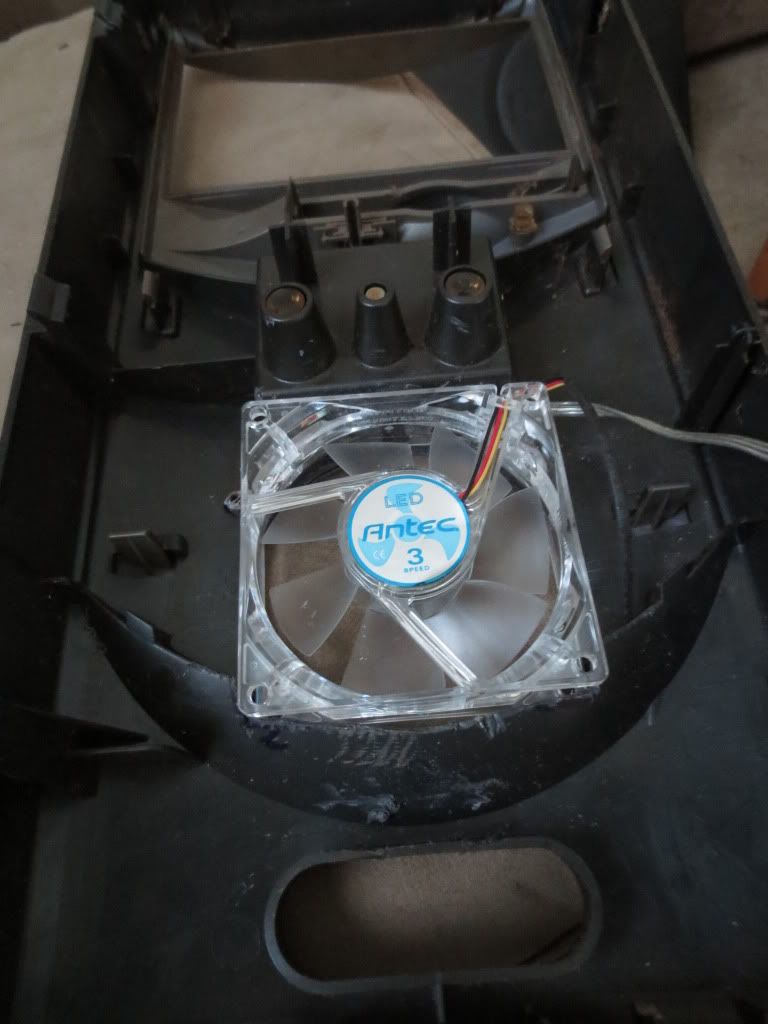
The Antec fan comes with an adapter so it can be plugged into the motherboard 3 pin jack or just the temperature wire:
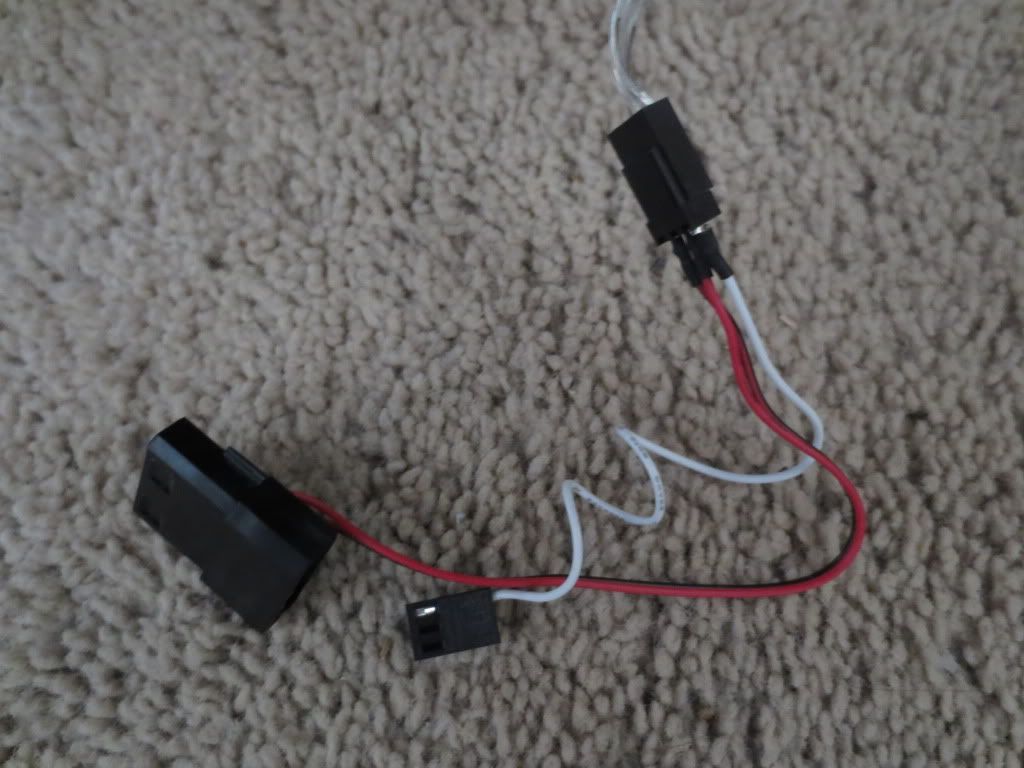
The power adapter can be plugged into a power supply male or female plug. That's what I used as I kept all other fans.
http://www.antec.com/pdf/manuals/tricool_install.html
Although the fan power wires are red and black, the connector connects the red fan wire to the yellow power wire.
The Antec fan also has a 3 speed switch to adjust the fan speed wired to a short lead.
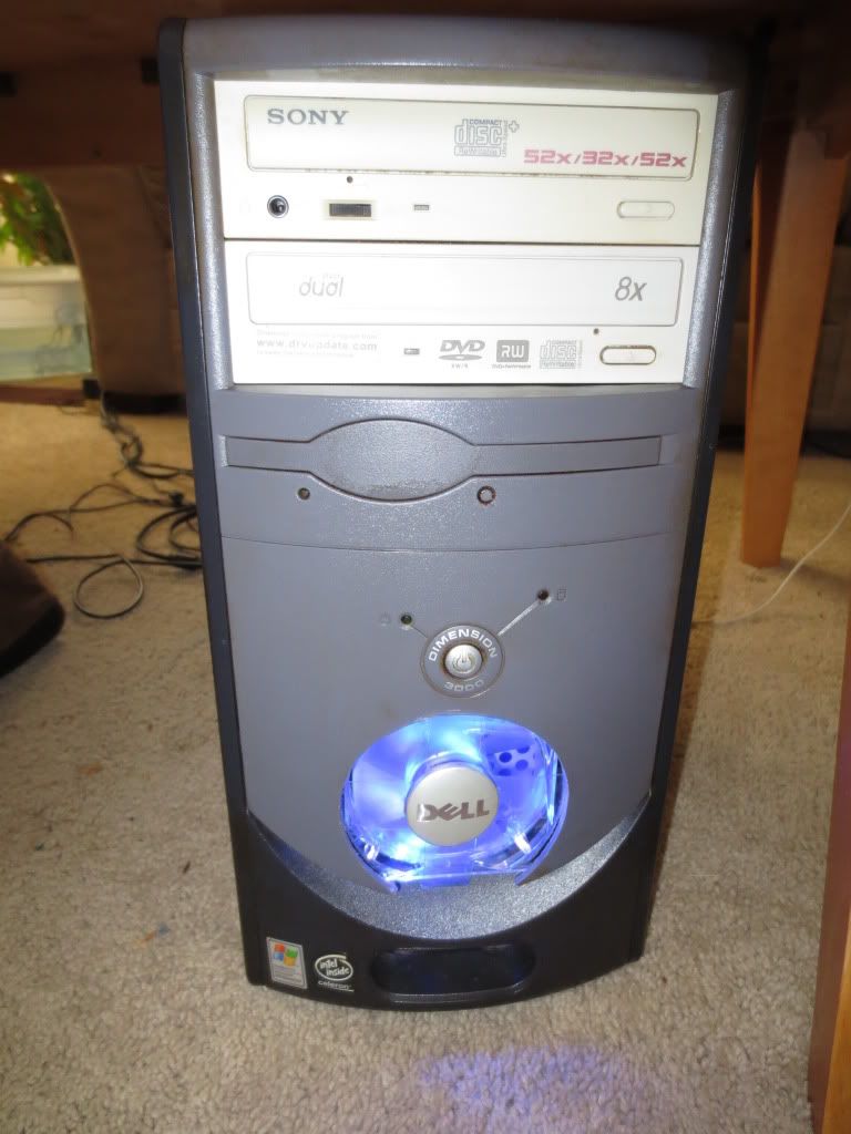
For whatever reason, Dell chose to block most of the air flow with a vertical hard drive mount:
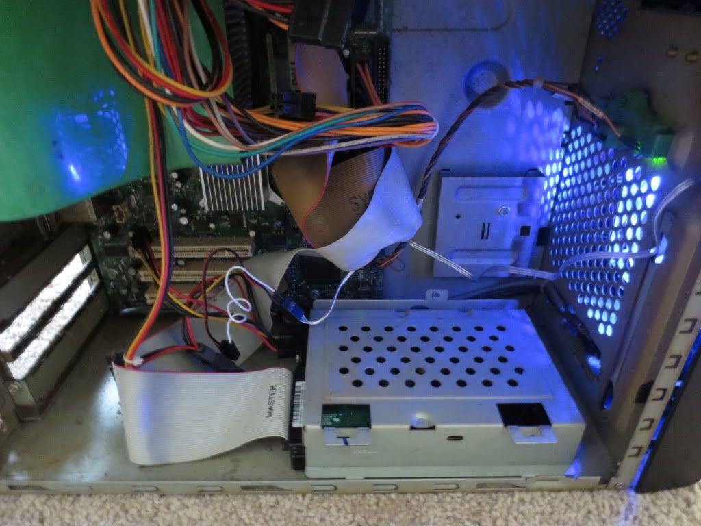
I laid it down to get better air flow and light up the interior better. The hard drive case was blocking most of those holes.
Statistics: Posted by burger2227 — Thu Jan 23, 2014 11:12 am
]]>
I had a 3 inch round hole saw I once used to put ventilation holes in my desk, but it took a bit of luck to drill the hole correctly.
I had to trim out the curved piece first so that the saw would fit between the smile and the power button. Can't move that!
I needed to cut a hole into the case for the fan wiring so I got a chance to try out my new Sonicrafter on steel:
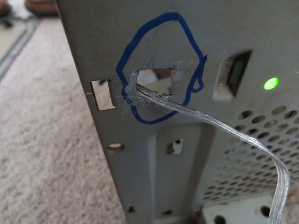
The metal cutting blade is kind of narrow compared to the wood blade, but it cut through with little effort. I just had to
move the tool back and forth to get it to plunge cut. It should make cutting holes for switches in cabinets a breeze!
Here's the finished product:
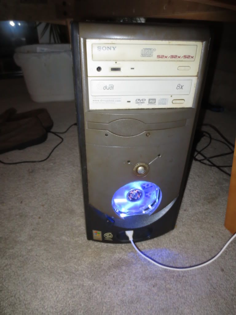
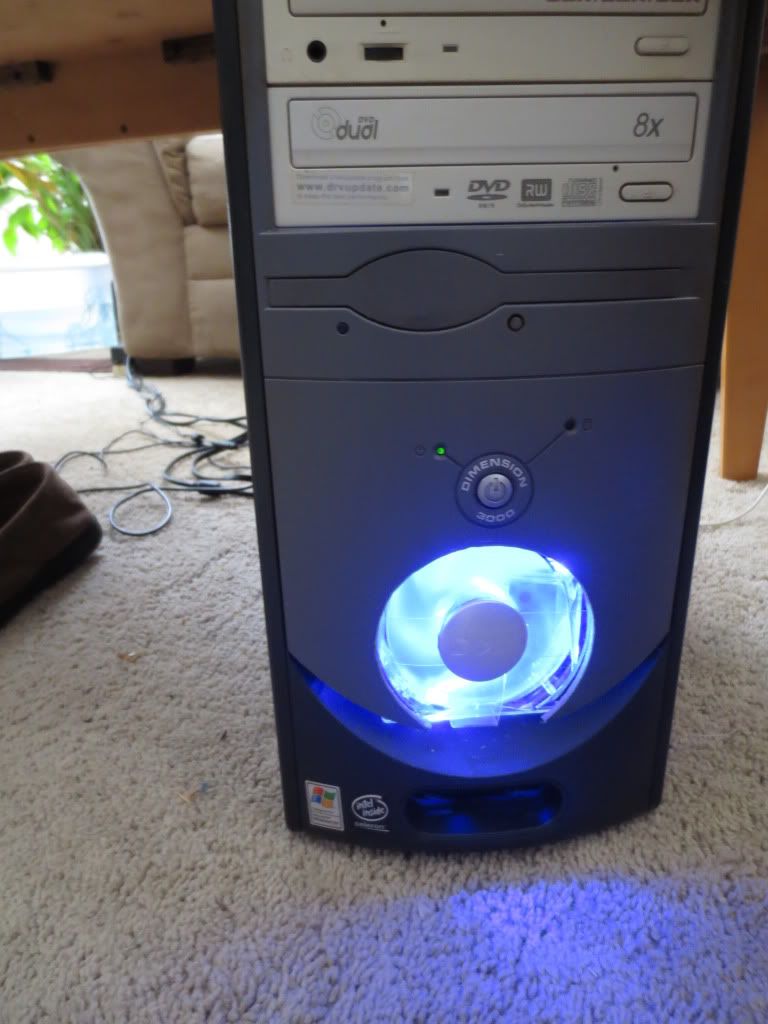
Here it is at night. Pretty bright. All it needs now is bigger eyes...
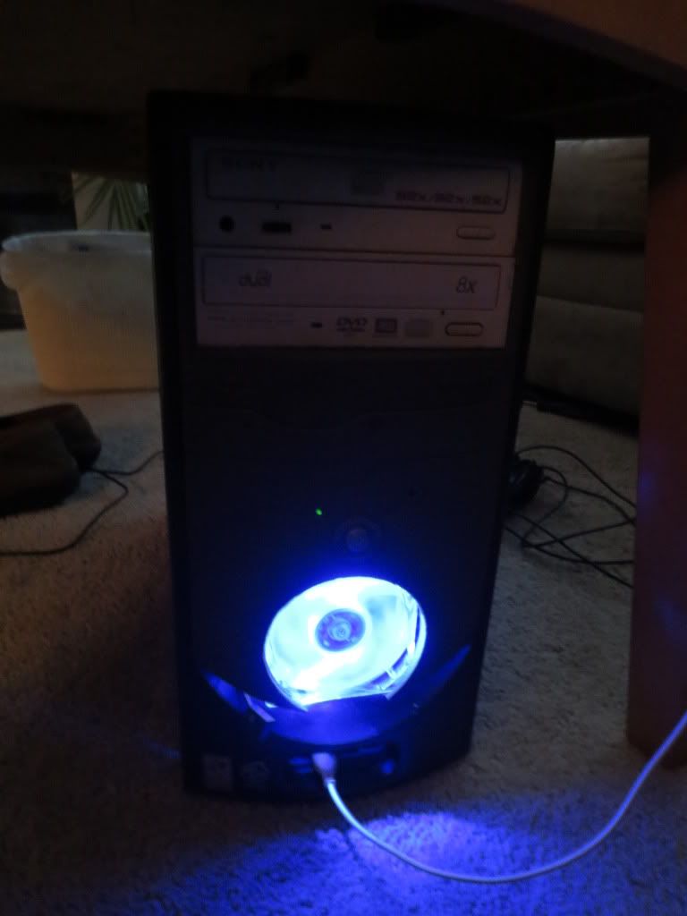
It was so bright that I decided to vent some light down into the USB area up front. That is kinda hard to see on the floor.
I may cut some more light vents and maybe even add some blinking LED eyes. It is smiling cause it no longer says Dell.
I drilled the starter hole through the name plate.
Statistics: Posted by burger2227 — Thu Jan 23, 2014 12:27 am
]]>